Construction of a Deep Shaft for Crossrail
WJ Whitepaper
Publication Credentials
AUTHORS:
A. M. McNamara, MSc, PhD
T. 0. L Roberts, PhD, CEng, FICE, CGeol, MCIWEM
P. R. J. Morrison, BAI, PhD, CEng, MIEI
G. Holmes, PhD
- WJ Groundwater Ltd, London, UK
DATE: 2007
Abstract
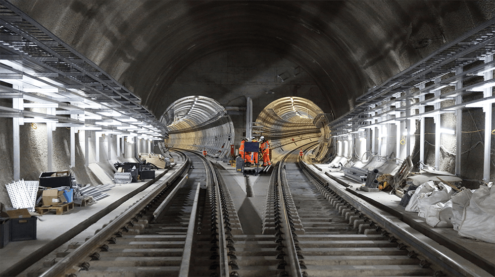
An 8·2 m diameter, 37·5 m deep shaft has been successfully constructed from within the basement of a new development, Moorhouse, near Moorgate in the City of London. Programme constraints led to the shaft being constructed after completion of the foundations, basements and most of the superstructure for the development. At its closest point the shaft is less than 2 m from the large-diameter piles that support Moorhouse, and the presence of these foundations placed tight constraints on acceptable ground movements associated with construction of the shaft.
The depth of the shaft is such that it penetrates through stiff London Clay and is founded at the bottom of the Lambeth Group. The paper describes the contingency measures to deal with potentially difficult ground conditions, including the water-bearing layers of the Lambeth Group. The construction processes included a complex temporary works dewatering system around the shaft, with the option to carry out additional dewatering from within the shaft during excavation.
Provision was also made for radial grouting to ‘restress’ the ground, to prevent long-term settlement of the Moorhouse piles, should the need arise. The success of the project was due, in no small part, to the detailed planning and consideration of contingency measures to deal with perceived risk.
1. Introduction
This paper describes the construction of an 8·2 m diameter by 37·5 m deep shaft. The shaft is part of the Crossrail works in central London, and is fonned of precast concrete segments. The segmental lining is deemed to have a temporary function (design life 20 years), and will in due course be fitted with the pennanent (secondary) cast-in-situ lining. The construction of the shaft was unusual in that it was carried out from within the IO m deep triple-level basement of the newly constructed Moorhouse building with the top of the shaft at approximately +0·5 mOD (2 m below the B2 level slab) and the final formation level at -37 mOD. The shaft was constructed by ‘underpinning’, and at its closest point was within 2 m of the large-diameter bored base-grouted piles supporting the new 16-storey building above. Significant problems arose during construction of the shaft, but careful planning, with contingency measures to respond to all key foreseeable eventualities, proved critical to the success of the project.
2. Project Outline
The Moorhouse development, the Crossrail shaft and the proposed adjacent running tunnels are shown schematically in Figure 1; out of view of Figure 1 is a proposed deep Crossrail station cofferdam box immediately beyond Moorhouse. The cofferdam box, tunnels and cross-passages to the shaft will be built as and when Crossrail is constructed. Detailed information on the design basis for the shaft can be found in Morrison et al.,1 but it can be summarised as follows.
(a) The shaft has a total length of 37·5 m through the London Clay and Lambeth Group strata.
(b) The internal diameter of the shaft is 8.2m; it was sized to accommodate the secondary lining and future Crossrail equipment.
(c) Primary shaft segment thickness is 0·35 m for the full depth of the shaft. Each ring comprises ten ordinary segments and two tapered joint segments.
(d) ‘Special’ segments were fabricated for the rings through which secondary dewatering of the Upper Lambeth stratum may have been necessary by means of inclined wells constructed from within the shaft.
(e) A concrete grade C45/55 mix (class 2 sulphate resistance) with 30 kg/m3 Dramix steel fibre reinforcement was used for segment construction.
(f) Low-friction bearings (taped and sealed polytetrafluraethylene (P1FE)) were used on every fourth circumferential joint to allow for relatively easy shear distortion of the shaft during the main phase of Crossrail construction (tunnels and cofferdam box). These P1FE bearings act to limit bending stresses in the shaft that would result in a substandard design factor of safety. All bearings (standard or P1FE) were 4 mm thick, thereby avoiding the need for special segments or gaskets.
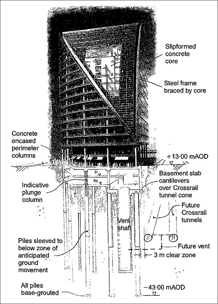
Figure 1: Schematic view of Moorhouse and Crossrail shaft and running tunnels (not to scale).
3. Preparation for Shaft Construction
The site stratigraphy consisted of 2·5-3·5 m of made ground and Terrace Gravel over about 30 m of London Clay, underlain by about 18 m of Lambeth Group clays, silts, sands and gravels, Thanet Sand and chalk. The shaft was founded in the Upnor Formation, which forms the basal stratum of the Lambeth Group. The Terrace Gravels are water bearing and form the upper aquifer in London. The Terrace Gravels had been removed for the basement construction, so shaft sinking commenced below the B2 basement level directly into London Clay. The granular horizons in the Lambeth Group form an intermediate aquifer, with pore pressures in central London often found to be partially reduced by the underdrainage in the lower aquifer. The Upnor Formation at the base of the Lambeth Group is often found to be in hydraulic continuity with the Thanet Sand below. The Thanet Sand and chalk form the lower aquifer in London. Groundwater levels in the lower aquifer have been substantially reduced by historical groundwater abstraction for water supply over the last 150 years. Following a reduction in abstraction, recovery in groundwater levels commenced about 50 years ago, but has recently been arrested by resumed abstraction because of concerns about the impact of raised water levels on London’s infrastructure.
Groundwater level monitoring and test pumping were carried out in the area of the shaft as part of the site investigation works. Water-bearing granular horizons were identified in the Lambeth Group, particularly at a level of -31 to -32 mOD and -35 to -38 mOD. Standing groundwater levels in these horizons were recorded at approximately -20 mOD (12 m excess head) and – 30 mOD (8 m excess head) respectively. Monitoring of groundwater levels in the Thanet Sand (the lower aquifer) indicated a standing groundwater level of -34 mOD, 4 m above the shaft formation level (Figure 2).
Pore pressures in the water-bearing granular horizons in the Lambeth Group needed to be fully controlled to facilitate the shaft construction in a safe manner that would not impact on the foundations of Moorhouse. This posed a particular problem, because the range of permeability in the Lambeth Group is very wide, perhaps 1 X 10- 4 to 1 X 10- 10 m/s owing to the banding of finer and coarser layers. Favourably, the water bearing layers that give rise to problems of groundwater induced instability generally fall within a narrower depth zone within the Lambeth Group. Such soils are of moderate permeability, with permeability of these fine sand or silt layers typically in the range 5 X 10-s to 1 X 10- 7 m/s. However, considerable variations in permeability may occur locally and, moreover, problems with in situ tests and sampling of these soils can make it difficult to assess permeability accurately. 2 In view of this, there were no measured permeability values obtained from the site investigation works.
Drawdown was also required in the Upnor Formation and Thanet Sand to below formation level to avoid the risk of base heave in the temporary condition during excavation to formation level. The Thanet Sand comprises a relatively uniform dense fme sand with varying silt content. The permeability ofThanet Sand is generally considered to lie in the range 1 X 10- 7 to 5 X 10- 5 m/s.3 The hydraulic response to pumping from wells installed in the Thanet Sand is complicated by the chalk below, which is generally in hydraulic continuity with the Thanet Sand and is of greater transitivity. For the Moorhouse shaft the drawdowns required in the Thanet Sand were modest, and it was considered feasible to achieve these by pumping from wells screened in the Thanet Sand only and avoid the need for pumping from deeper wells with response zones in the chalk. A major disadvantage of using chalk wells at Moorhouse would have been higher well yields, which would have presented difficulties with disposal and discharge.
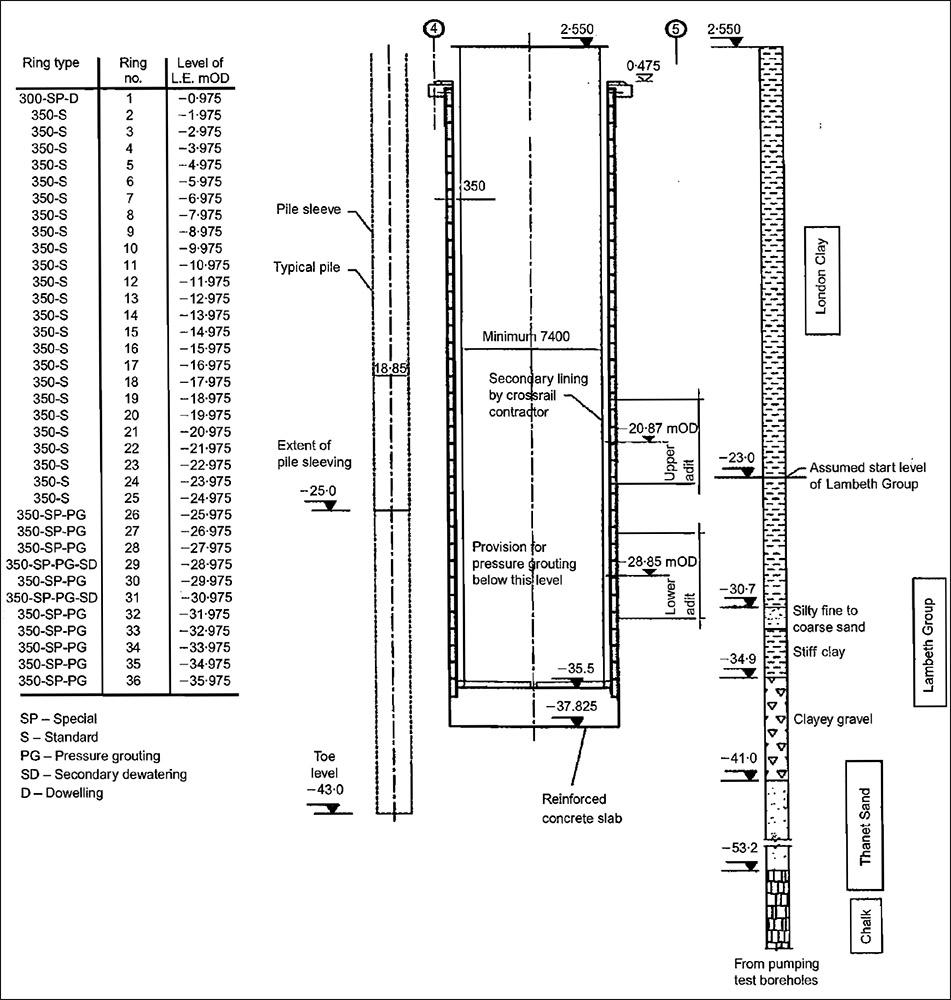
Figure 2. Section of draught relief shaft wit pile and ground condition details (dimensions in mm, elevations in mOD).
The outline specification for the dewatering system used is given in Table 1. This involved installation of a total of 17 dewatering wells around the shaft to draw down water levels/ pressures in the Lambeth Group and Thanet Sand strata.
The shallower wells were targeted at the granular horizons in the Lambeth Group, and used ejectors driven from a pumping station located at the new B2 level basement at 2·5 mOD. The well annulus was grouted through the London Clay to provide a seal. This allowed the ejectors to generate a vacuum to promote drainage of the target horizons. The deeper wells were targeted at both the Thanet Sand and the base of the Lambeth Group. These were pumped with electric submersible borehole pumps installed close to the base of the wells.
The dewatering system was sized to accommodate comfortably the anticipated discharge of up to 5 1/s, the majority of which was expected to be derived from the Thanet Sand. In the event, the actual discharge was approximately 3 1/s. The discharge was led to a tank at the B2 level, from where it was pumped to the main sewer. The dewatering system was provided with full backup facilities, including auto-start standby generators and standby pumps. The discharge flow, piezometers and pump operation were monitored with an online data-logger system, which also provided an alarm function via a telephone link in the event of a system fault.
The site temporary power supply proved to be unreliable, and during the early stages of dewatering it was found that the supply was frequently interrupted, albeit for short periods; with hindsight, a dedicated power supply should have been provided. Any interruption meant that the ejectors, which were dealing with the small flows from the Lambeth Group, would need to be manually restarted. The deep wells in the Thanet Sand, which were critical for a considerable period of time when the shaft excavation neared completion until the base plug was constructed and cured, automatically restarted.
Experience gained during installation and testing of the system indicated that groundwater recovery time was about 2 h in both the Thanet Sand and Lambeth Group. The travel time to site for someone to restart the system in the event of failure was about 1 h. In view of the critical nature of the works it was decided to have an operative permanently on site monitoring the dewatering system during excavation through the water bearing layers of the Lambeth Group and until the shaft base plug was concreted and cured. This decision was vindicated when both the electricity supply and the alarm system failed (owing to the telephone wire having been accidentally cut) at 2 o’clock one morning. In this instance the system was manually reset without any interruption to shaft construction, even though no automatic alarm had been triggered.
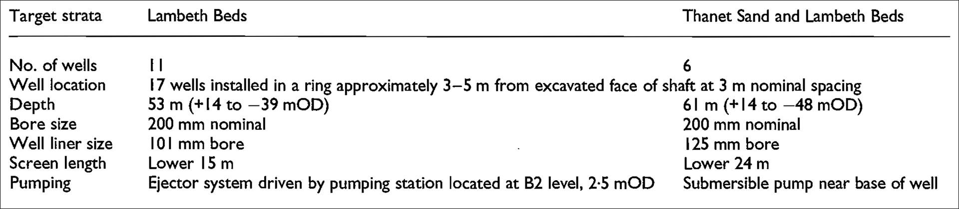
Table 1. Outline specification for dewatering system.
4. Management and Planning of Construction
Skanska UK Building managed the shaft construction as the design-and-build contractor, but always in close collaboration with the design team from Arup Geotechnics and the key specialist subcontractors, WJ Groundwater and Skanska Cementation Mining, as well as with the client for Moorhouse, Greycoat Ltd, and Crossrail, which was supported by its category 3 checker, Geotechnical Consulting Group. Frequent meetings were held for a significant period before and during construction to ensure that all eventualities and concerns were properly addressed.
All parties were able to scrutinise all aspects of the design and proposals for construction. This meant that, upon commencement of construction of the shaft, the team members operated with a spirit of openness and cooperation that undoubtedly aided the project and allowed any new problems to be addressed and resolved collectively with a minimum of disruption. During shaft excavation a weekly review meeting was convened in which all parties, including the category 3 checker for Crossrail, were able to discuss monitoring results and any other issues of concern.
5. Drilling for Dewatering and Instrumentation Installation
All activities associated with preparation for and construction of the shaft were programmed to be off the critical path of the main Moorhouse construction project. This allowed a high degree of flexibility over timing, but it meant that the physical constraints imposed by the site conditions often made access extremely difficult. The first preparatory work for shaft construction was installation of the dewatering system and instrumentation. When these works commenced, the Moorhouse superstructure was nearly complete, and a 14 t drilling rig had to be accommodated on the ground-floor slab at +13·42 mOD with only 7·5 m of headroom (which was achieved by temporarily omitting a mezzanine slab). Figure 3 shows schematically the set-up for drilling, and Figure 4 shows the reality of access difficulties on site.
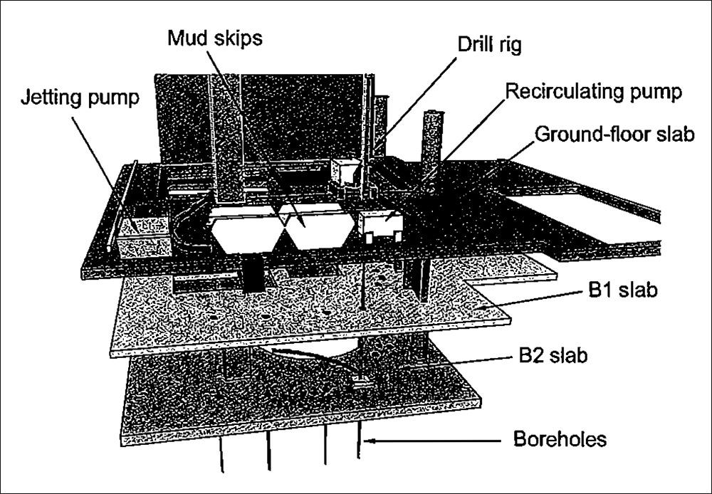
Figure 3: Schematic showing dewatering and instrumentation installation on site.
Drilling was carried out from the ground-floor slab through two basement voids, as it would have been impossible to accommodate the drilling rig within the basement, where headroom was extremely limited. The ground-floor slab in the area of the shaft was dominated by large service holes for future Crossrail use, which at this stage were temporarily infilled with precast concrete panels to allow access. However, it was also necessary to strengthen the ground-floor slab over the entire area to allow the heavy plant associated with shaft construction to operate. Despite the absence of the mezzanine slab, it was still frequently necessary for the drilling rig to lower its mast to avoid clashing with dciwnstand beams at the underside of the first-floor slab when moving between drilling positions. Although the rig had reasonable access over the position of the shaft at ground level, the profile of the basement structure below ground level dictated the use of wells inclined at angles up to 6° in several positions to ensure that the spacing and position of the wells at depth were correct.
This further added to the complexity of the drilling operation, and required careful setting out of temporary access holes in the ground, B1 and B2 slabs to allow for the angle of the drill string. Table 2 shows the structural slab levels and sequence of stratification below the new structure.
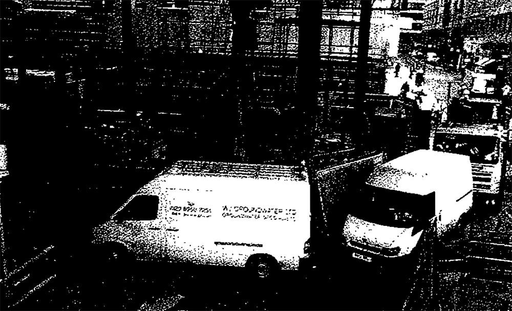
Figure 4: Congested site access with 14ft drilling rig operation on ground-floor slab.
6. Instrumentation and monitoring
An extensive monitoring system to determine ground movements associated with shaft construction was devised and implemented. The main aim was to enable cumulative movements to be observed as construction progressed, so that measures could be taken to prevent excessive movement, and also to detennine the need, if any, for remedial measures following completion of the shaft. Monitoring included the use of precise levelling, inclinometers, extensometers and piezometers. The same drilling rig used to install the wells was also used to install the instrumentation, as shown in Figure 5. Precise levelling of studs at ground-floor level was carried out throughout the period of shaft construction. Prior to the commencement of shaft construction, these levels were related to corresponding studs at B1 and B2 levels. Following completion of the shaft, the stud levels at ground floor were again related to those at B1 and B2. This method of working was thought to enable increased accuracy, as it was not necessary to transfer readings from basement level to the temporary benchmark about 80 m from the site in Moorf1elds more than twice (once at the start of the exercise and once at the end). However, this approach assumed that the ground floor slab and B2 slab would move together, which may have been a limitation.
Monitoring of the studs commenced one week before commencement of the shaft excavation to enable baseline readings.to be established. The studs were then monitored once a week throughout the period of shaft construction. Once baseline readings were established for all other instrumentation, they were monitored twice a week initially, with increased activity during excavation through the Lambeth Group.
The performance of the dewatering system was assessed throughout the construction period, using an array of nine piezometers installed in three boreholes. The boreholes had three piezometers, each of which had a response zon inone of the water-bearing layers identified: the two granular horizons in the Lambeth Group and the Thanet Sand. The piezometers in each borehole comprised one standpipe and two vibrating-wire transducers. This allowed each of the three water-bearing horizons to be monitored with one standpipe piezometer and two vibrating-wire transducers installed in sand cell response zones.
The piezometer installation details are summarised in Table 3. Continuous monitoring was achieved using vibrating wire transducers connected to a data logger. Similar systems have been shown in the past to be reliable; however, as a precautionary measure the standpipe piezometers were also manually dipped weekly to check for anomalies. Monitoring of piezometers in the period before and during excavation within the Lambeth Group was essential to determine the effectiveness of the dewatering system. Prior to commencement of shaft excavation, a trial of the dewatering system was carried out to assess its performance with respect to the design intent, and to undertake a switch-off test. The switch-off test gave information on pore pressure recovery rates, which provided a rational basis for reviewing monitoring arrangements, standby plant and call-out facilities.
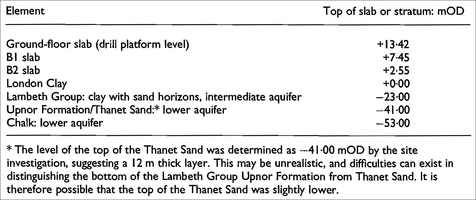
Table 2: Structured slab levels and sequence of stratification below the Moorhouse structure.
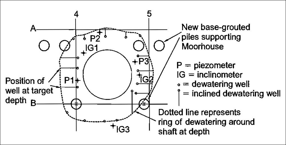
Figure 5: Layout of dewatering wells, piezometers and inclinometers around shaft position.
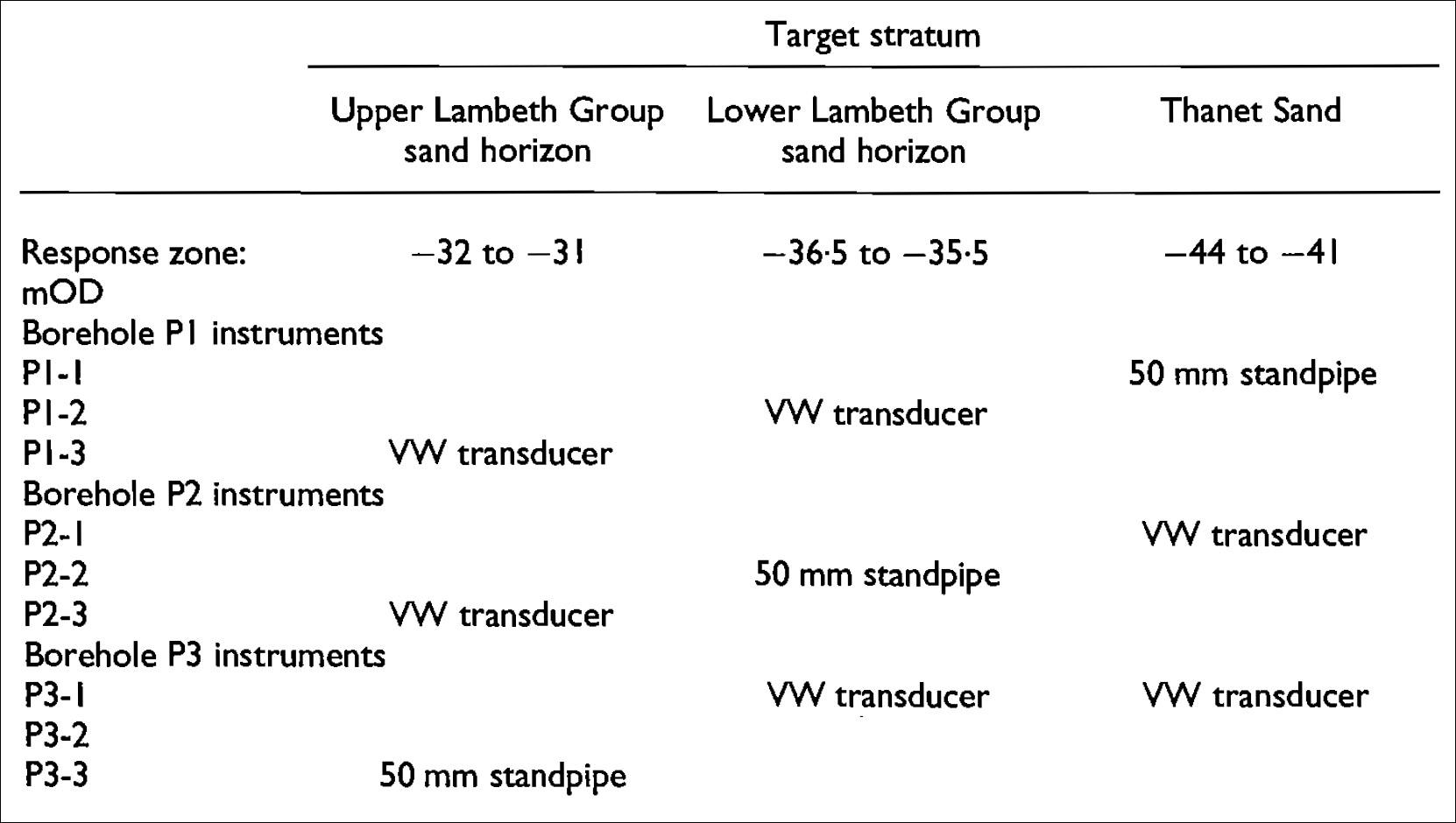
Table 3: Summary of piezometer installation around shaft.
7. Shaft Construction
7.1 Logistics
The permanent columns of the new Moorhouse superstructure imposed severe restrictions, particularly on the movement of excavated spoil across the ground-floor slab. Traffic congestion around the site was such that all vehicle movements associated with the project needed to be carefully controlled within a restricted period between 8·00 am and 6·00 pm Monday to Friday owing to the close proximity of residential accommodation, and enforced via a Control of Pollutions Act, 1974, Section 61 noise-restriction agreement. This proved to be less of a limitation on shaft construction activities than the fact that disposal of the excavated spoil could not continue beyond 4·00 pm because of the working hours of the tip. Excavation and segmental ring building was a continuous 24 h operation between 8·00 am on Monday morning and 6·00 pm on Saturday, and there was consequently a need to be able to store a substantial volume of excavated material on site.
Excavation for each 1 m deep ring generated about 100 m3 of spoil (with bulking), and allowance was made for storing up to two rings’ worth on site. A muck store was formed on a ground-bearing area of the Bl slab. The store was filled by placing the muck skip on a tipping frame at ground-floor level (Figure 6). The muck skip was moved from the shaft area to the store area by means of a curved runway beam supported on temporary steel gantries: one over the shaft, and the other outside the superstructure building line but supported on the -basement structure. A 20 t excavator was used to empty the muck store during the day. Limited space and restrictions on slab loading meant that only two complete rings of shaft segments could be stored on site at any time; also, segment delivery had to be carefully coordinated with other deliveries and muck-away. Twenty-four-hour working imposed additional restrictions relating to noise in a residential area. This was overcome by the erection of an acoustic screen that was designed to prevent noise rising above ambient levels at night around the site. The acoustic screen reduced ventilation in the area of the shaft, and night shift work was carried out in uncomfortably hot conditions.
The shaft excavation was carried out using a 6 t track mounted excavator, which was lowered into the shaft using the gantry hoist and lifting slings. The excavated spoil was loaded into a 5·5 m3 bottom-opening circular skip, which was hoisted up the shaft and discharged into the store using the curved runway beam and tipping frame (Figure 7). Final trimming of the ground was carried out using hand-held clay spades to allow a gap of approximately 40 mm behind the segments; the gap was specified not to exceed 100 mm at any location (Figure 8).
Only sufficient depth of ground at the formation was excavated in order to allow the building of the segments. This was generally kept to a maximum of 200 mm below the segments, which provided sufficient space for the ring build. However, deeper excavation was required locally at the key segment to allow it to be lifted into position with the additional space needed to accommodate the radial taper (Figure 9).
The segments were mounted on a building frame, and were moved into position using a track-mounted hoist located around the shaft perimeter. The segments were connected with spear-bolted cross-joints and tightened to the correct torque to compress the sealing gasket. The segments were fitted with EPDM (ethylene propylene diene M-class rubber) gaskets at the factory, with bitumen packers on all the segment joint faces. The ordinary segments were built first, followed by the taper joint segments; the ring was then checked for level, and the position at each segment and thereafter adjusted as necessary.
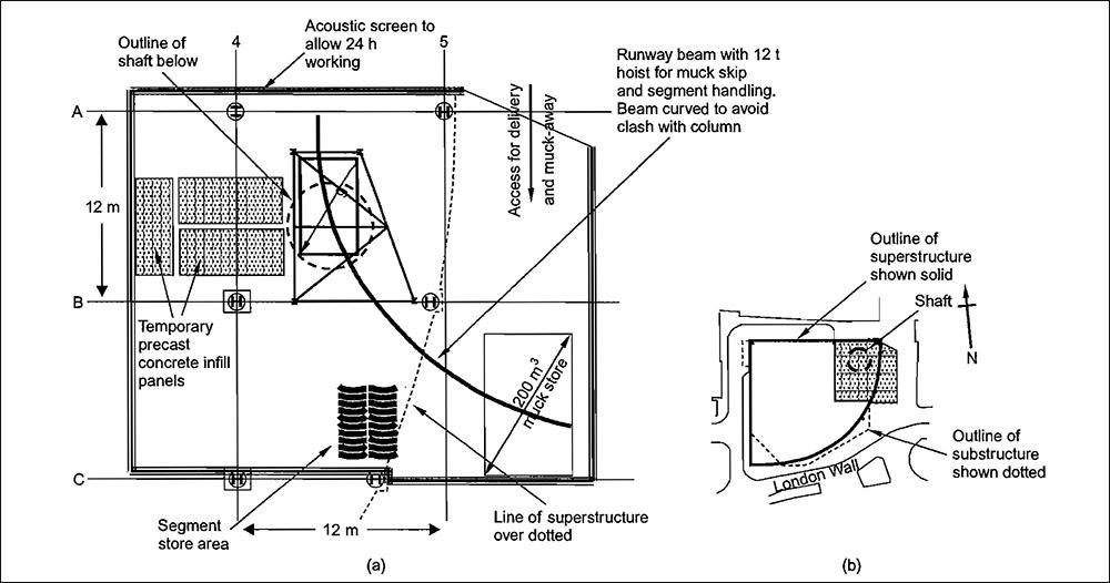
Figure 6: Layout of ground-floor slab during shaft construction: (a) ground-floor plan in area of shaft; (b) key plan showing area of shaft within Moorhouse site.
Each ring of segments was bolted, using through-bolts, to the underside of the ring above. The joint between each ring had a 4 mm polymer or PTFE packer fitted, along with alignment dowels, and each ring was also rotated relative to the last ring to stagger the cross-joints. Where necessary, additional polymer packing strips were inserted on the ring face (but not across the gasket) to correct for any parts of the ring that were out of level. Grouting was carried out as soon as possible after the ring building was completed. A seal was formed to prevent grout loss from the back of the segments by using air hose, cement bags and clay to ‘fluff up’ the joint. The ring was then grouted using an ordinary Portland cement grout, with a water/cement ratio of approximately 0·4, which was mixed in a vertical grout mixer on the surface and pumped down a grout hose and through grout holes in each segment. Grouting commenced in one location and was then continued systematically around the full ring. Each segment had a grout vent at the top, and grouting continued until grout was present at the vent hole, which was then capped off. The grouting operation typically took 2-3 h, with grouting pressures kept below 1 bar (105 Pa) owing to the need to avoid leakage from beneath the bottom of the segments.
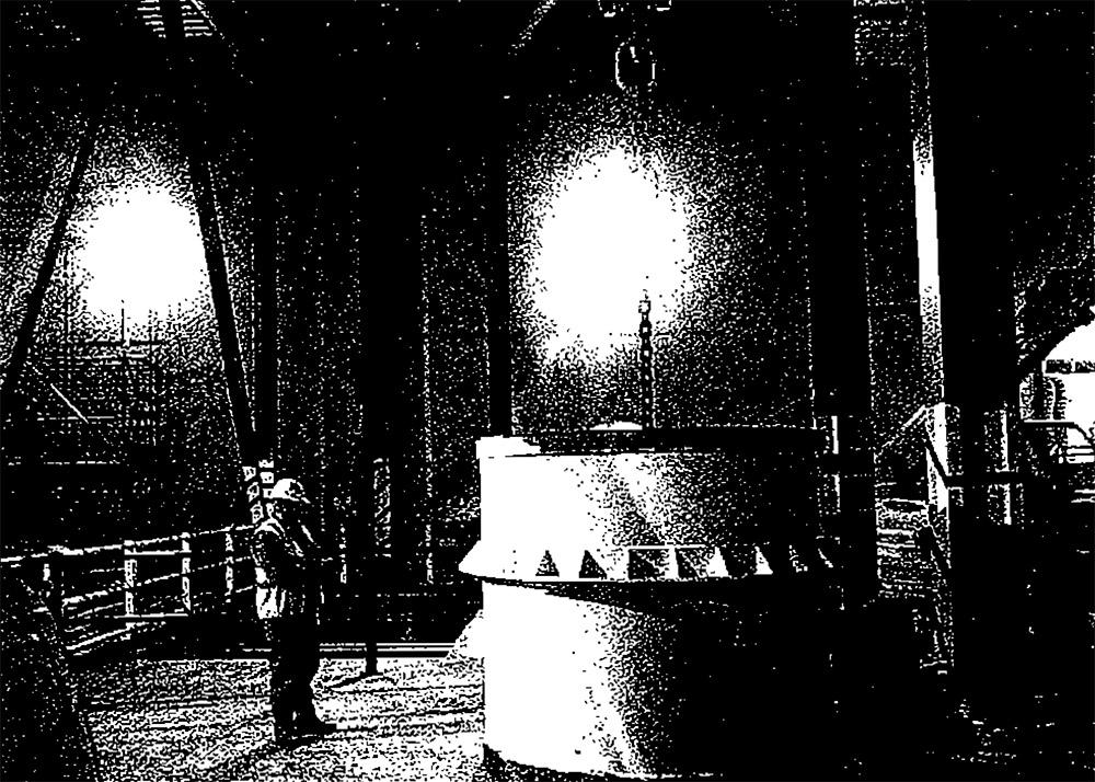
Figure 7: Muck skip under runway beam on ground-floor slab immediately before commencement of shaft construction. Moling hole in background.
Figure 8: Final trimming to allow a gap not exceeding 100mm behind segments was carried out using clay spades.
Figure 9: Overdig at position of key segment.
7.2 Predicted and Measured Group Movements
Details of the design associated with the shaft construction are given in Morrison et al.,1 and the calculated and measured deformations at inclinometer IGl are shown in Figure 10 for four intermediate dig stages and the final conditions with the base of the shaft constructed. Significant differences exist between the measured and predicted displacements associated with IGl, but this is not unexpected. The soil model used in the analyses1 was moderately conservative, although not to the point where the results of the analyses could have suggested a different method of construction. In addition, the analyses ignored the stiffening effect of the 1·B m diameter piles of the Moorhouse building, which would almost certainly have affected the displacement oflGl in particular, since this inclinometer was positioned between the pile and the shaft.
The material exposed to the water was stiff, fine-grained, overconsolidated clay, and was relatively impermeable. Water could not be expected to penetrate very far into the excavated surfaces, especially given the duration of exposure, and as a result significant softening did not occur. When the shaft was entered, following removal of the water, the softened material was found to extend to a depth of about 100 mm. It would seem reasonable to assume that much of this material was left over excavation arisings that had not been removed from the shaft. Inclinometer tube profiles showed that the maximum inclinometer movement was 2 mm. This movement is thought to be genuine but, when viewed in the context of previous and subsequent displacements, was not particularly significant or excessive.
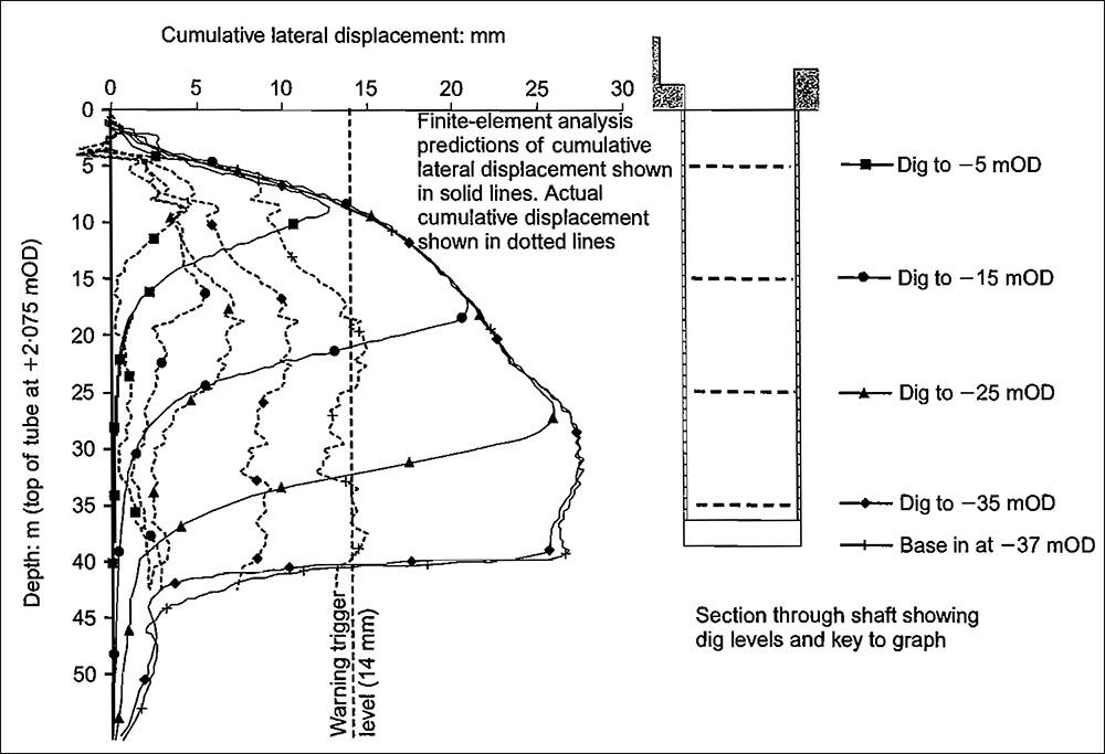
Figure 10: Predicted and measured ground movements during construction of shaft at inclinometer IGI.
7.3 Shaft Flood
Excavation and construction of rings proceeded as planned until the excavation reached ring 8, whereupon the ring was built and grouted at the end of a Friday night shift, and the shaft was left until the following Monday morning. In the early hours of Sunday morning a coupling on the site water main failed, causing extensive flooding to the basement of Moorhouse, including the partially constructed shaft. The water from the main filled the shaft to a depth of about 2 m, implying about 100 m3 • Excavation of the shaft was at a relatively early stage, in a substantial layer of stiff London Clay, and the formation was at about -8·5 m0D. Pumping to remove the water by means of a high-lift submersible pump commenced at about 4·00 pm on the Monday, and this operation was complete by mid-evening, a few hours later. The water therefore remained in the shaft for a maximum period of about 36 h. Excavation for ring 9 was completed by the morning of the Wednesday, at which point the ring was built.
The material exposed to the water was stiff, fine-grained, overconsolidated clay, and was relatively impermeable. Water could not be expected to penetrate very far into the excavated surfaces, especially given the duration of exposure, and as a result significant softening did not occur. When the shaft was entered, following removal of the water, the softened material was found to extend to a depth of about 100 mm. It would seem reasonable to assume that much of this material was left over excavation arisings that had not been removed from the shaft. Inclinometer tube profiles showed that the maximum inclinometer movement was 2 mm. This movement is thought to be genuine but, when viewed in the context of previous and subsequent displacements, was not particularly significant or excessive.

Figure 11: Trial pit at perimeter of shaft in water-bearing strata of Upper Lambeth Group.
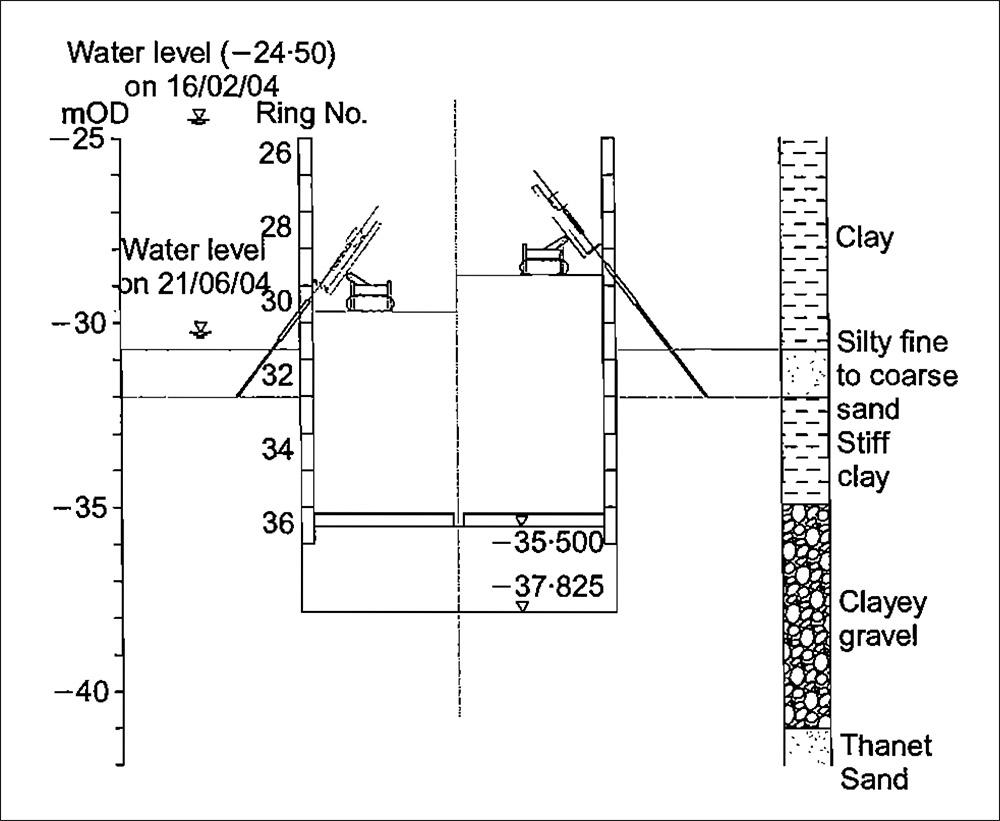
Figure 13: Secondary dewatering system using inclined wells from within shaft.
7.4 Secondary dewatering in the Upper Lambeth Group
Throughout construction of the shaft, the ground conditions and dewatering performance and output were monitored and recorded by the shift engineer as excavation proceeded. Although excavation through London Clay was straightforward, probing ahead of the excavation, from within the shaft, was carried out when the shaft was approximately 3 m above the upper_ granular horizon in the Lambeth Group (between -31 m0D and -32 mOD} and the hole was checked for water (Figure 11). This was because, although the dewatering system functioned well, the water levels monitored in the Upper Lambeth Group (notably between -30·7 m0D and -32 m0D} remained approximately 1 m above the design level of 0 m excess head of water (Figure 12).
As the excavation approached the level at which two of the three piezometers were indicating about 1 m of water, the issue manufactured with provision for drilling the inclined wells for secondary dewatering. These could be installed at any level but, owing to the offset nature of the joints in alternate rings (to maximise the stiffness of the shaft), the positions of the individual wells were governed not only by the ring elevation but also by its orientation. These restrictions were, in tum, exacerbated by a third logistical problem in that there was only sufficient space on site to store two complete rings of segments. This meant that a special ring of segments would have to be installed almost immediately if it was brought to site. The time taken to install the secondary dewatering wells would in itself result in increased movements around the shaft.
Therefore the decision to use secondary dewatering and the timing of its installation was critical.
Shaft excavation and construction continued until trial pits could be excavated from about 2 m above the water-bearing layer. Three trial pits at third points around the perimeter of the shaft remained dry following excavation. On this basis all parties agreed to proceed with excavation through the water bearing layer. Upon excavation the silty sand appeared relatively dry, but during the course of the ring build, about 2-3 h, small amounts of material continually fell from the sides all around the shaft (Figure 14). At this point the piezometer reading had dropped and recorded a small suction. When the ring build was complete, the average space behind the segments was about 400 mm, gauged from the quantity of grout that was used to fill the void. However, the slumping of material that took place during the ring build, and continued until grouting was complete, means that it was difficult to know the real extent of the overbreak, as it could not be seen. Excavation continued for subsequent rings, and the piezometer reading recovered to show 1 m head (Figure 12). The additional movement resulting from excavation through this layer became apparent from the inclinometers near to the shaft. A maximum displacement of 7 mm was recorded on inclinometer IG2 (Figure 15). This movement represented nearly 500/o of the total movement for the entire shaft construction.
Excavation for the base plug of the shaft entailed undermining the bottom ring of segments by 2 m in a layer of clayey coarse gravel to fix a heavily reinforced cage. This excavation was nearly twice the depth of the ring excavations, and greater movements could therefore be expected. Additionally, the excavation was to remain open for much longer while the base plug was constructed. This layer was the Upnor Fonnation, which had been targeted by the ejectors with the aim of eliminating the excess head of about 5 m. All of the piezometers around the shaft indicated that the head had been successfully drawn down, and the excavated faces were gunited to maintain stability during the two weeks needed to fix steel and pour the base. Dewatering continued until the base plug achieved design strength, and monitoring continued for a further month. Inclinometer readings showed additional movement during this period, with the most movement being recorded at IG2 (Figure 16), where a warning trigger level was reached. However, considering the time taken to complete the construction of the base plug, this was not excessive, and the overall movement remained well inside the action threshold.
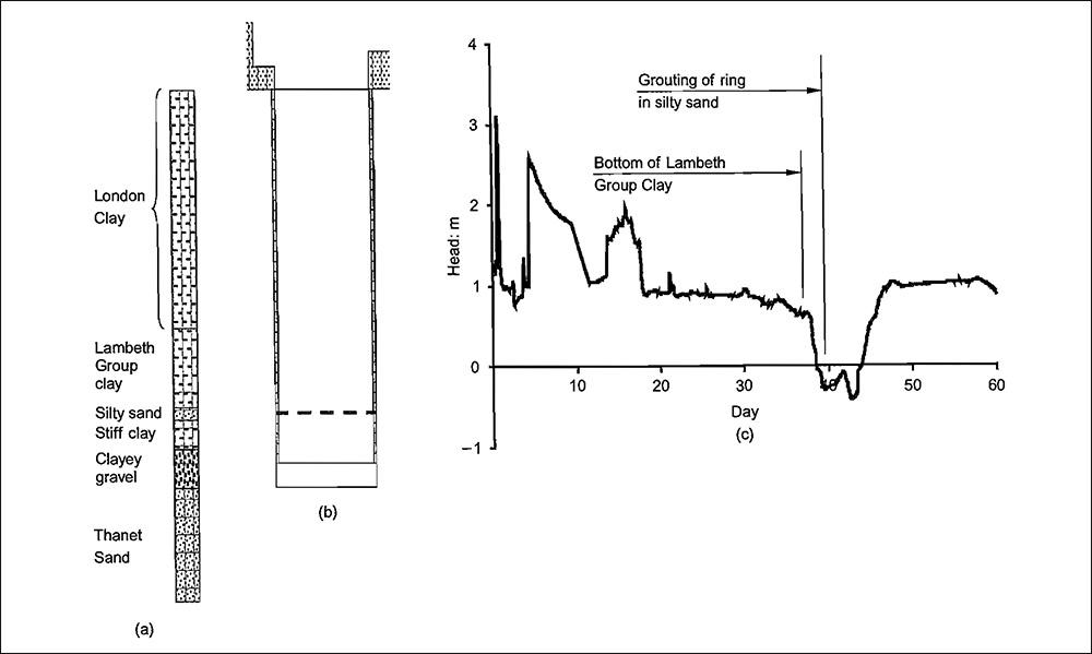
Figure 12: Head in Upper Lambeth Group during construction of shaft: (a) typical borehole; (b) section; (c) Upper Lambeth Group water levels.
7.5 Grouting to Restress the Ground
Any need for grouting to restress the ground around the shaft was dependent on the results of the ground monitoring. If the acceptable inclinometer movement limits were exceeded then the grouting was deemed necessary to ‘restress’ the ground around the shaft and adjacent piles. It should be noted that grouting was not intended as remedial work to the new Moorhouse development per se, but as a measure that would help to safeguard Moorhouse in the event of future tunnel and station box construction associated with Crossrail. If required, the grouting would be carried out after the shaft was complete and the base concreted. Several of the shaft rings had additional large grout holes, which could be used to allow radial drilling and subsequent grouting to be carried out. In the event, the maximum movement in relation to a trigger level was about 15 mm on inclinometer IG2, which exceeded the warning trigger movement of 14 mm but did not exceed the action trigger movement of 21 mm.
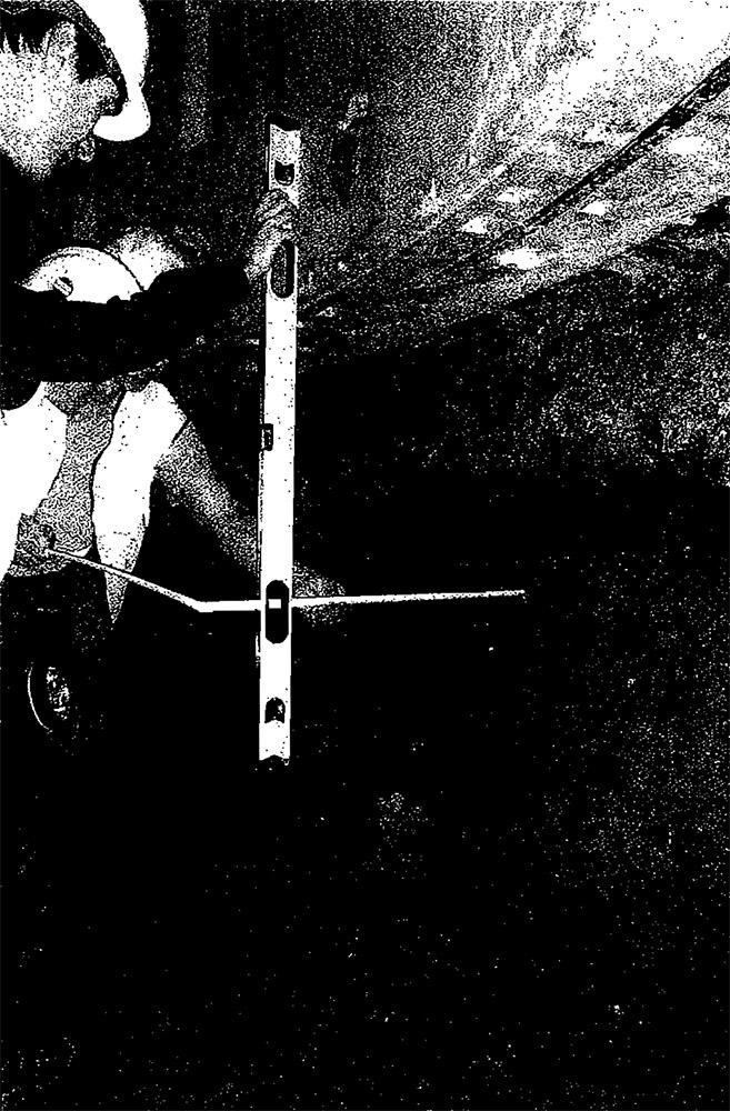
Figure 14: Silty sand slumping from excavated face during ring build in water-bearing layer in Upper Lambeth Group.
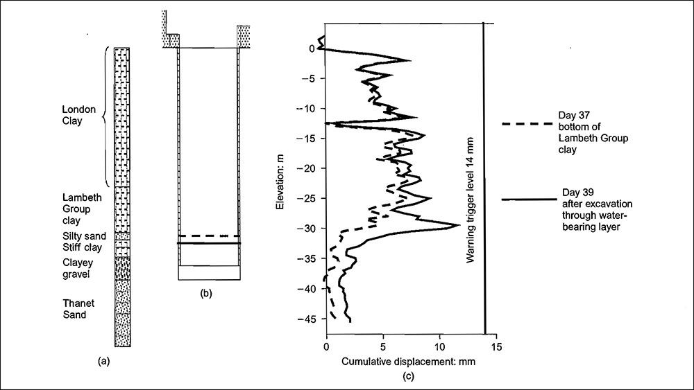
Figure 15: Inclinometer data reflecting movement associated with excavation through water-bearing layer in Upper Lambeth Group: (a) typical borehole; (b) section; (c) inclinometer data for IG2.
8. Conclusion
An 8·2 m diameter by 36 m deep shaft has been constructed within the basement of a new 16-storey building. The shaft has been constructed through about 20 m of London Clay and then through the soils of the Lambeth Group, where two water bearing layers were encountered . At its closest point the shaft was within 2 m of the new, heavily loaded piled foundations of Moorhouse. The proximity of the existing foundations and the influence of the proposed developments associated with Crossrail posed significant problems to the design and construction team with respect to limiting the impact of the shaft’s construction on Moorhouse. A sophisticated dewatering system was devised and installed to enable excavation and construction through the Lambeth Group, and also to enable the shaft to be excavated to within 2 m of the underlying Thanet Sand. Elaborate precautions were taken to ensure that construction solutions were in place to deal with foreseeable events, and a detailed monitoring exercise was carried out to help control ground movements and thereafter demonstrate that ground movements did not exceed acceptable limits.
The movements that did occur were linked very strongly to two significant events in the shaft construction. The first event was excavation through a layer of water-bearing silty sand that had been dewatered but still contained about 1 m excess head.
Although this layer was only about 1 m thick, and the excavation was rapid, this accounted for nearly 50°/o of the maximum horizontal movement measured by an inclinometer near to the shaft. The second event was excavation below the silty sand layer and construction of the base plug. This was carried out over a period of 18 days and involved a deeper excavation than had been necessary for the precast concrete rings. This process occupied approximately 30°/o of the time taken to construct the entire shaft, and contributed another 8 mm or just over 500/o of the maximum horizontal movement at the base of the shaft.
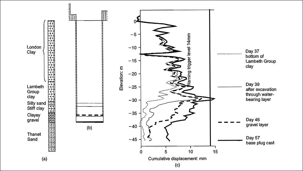
Figure 16: Inclinometer data reflecting movement associated with excavation through clayey gravel and construction of base plug: (a) typical borehole; (b) section; (c) inclinometer data for IG2.
Acknowledgements & References
Acknowledgements
The authors thank their colleagues for their contributions leading to this paper, and in particular Chris Field and Tony Boorer of Skanska UK Building, Paul Judge of W J Groundwater Ltd, and Alan Winter of Arup Geotechnics.
References
- MORRISON P. R. J., McNAMARA A. M. and ROBERTS T. 0. L. Design and construction of a deep shaft for Crossrail. Proceedings of ICE-Geotechnical Enginee ring, 2004, 157, No. 4, 173- 182.
- PREENE M. and ROBERTS T. 0. L. Groundwater control in the Lambeth Group. Proceedings of ICE- Geotechn ical Engineering, 2002, 155, No. 4, 221-227.
- ELLISON R. A. Geology of London: Special Memoir for 1:50 ,000 Geological Sheets 256 (North London), 257 (Romford), 270 (South London) and 271 (Dartford). British Geological Survey, Keyworth, Nottingham, 2004.
Link
To read the full, original published paper, please click on the link below: