Geotechnical Engineering for the Medway Tunnel and Approaches
WJ Whitepaper
Publication Credentials
AUTHORS:
• Q. Leiper, BSc, MSc, CEng, FICE, FIHT, CGeol, FGS
• T. Roberts, BSc, PhD, CEng, FICE, FGS, MC!WEM
• D. Russell, BSc, MSc, PhD, CEng, MICE
DATE: 2000
Abstract
The design and construction of the Medway immersed tube tunnel and approach structures required a thorough investigation of the site and a detailed understanding of the geology and geotechnical behaviour of the soils. The paper describes the ground investigation and discusses how the design accommodated the ground conditions to allow the tunnel and approach structures to be safely and efficiently constructed. Two main geotechnical challenges are described; the approach embankments and the casting basin in which the immersed tube tunnel sections were constructed. Part of the approach embankment was constructed over very soft soils.
The construction made use of vertical drains, stage construction and preloading to ensure that the embankment was constructed economic ally within the available programme. The immersed tube tunnel sections were constructed in a casting basin next to the river. The design of the casting basin required careful consideration of the stability of the temporary slopes and the dewatering system had to deal with large quantities of water without causing significant settlement of some sensitive nearby structures.
These two areas are discussed and details of the construction and performance are provided.
Introduction
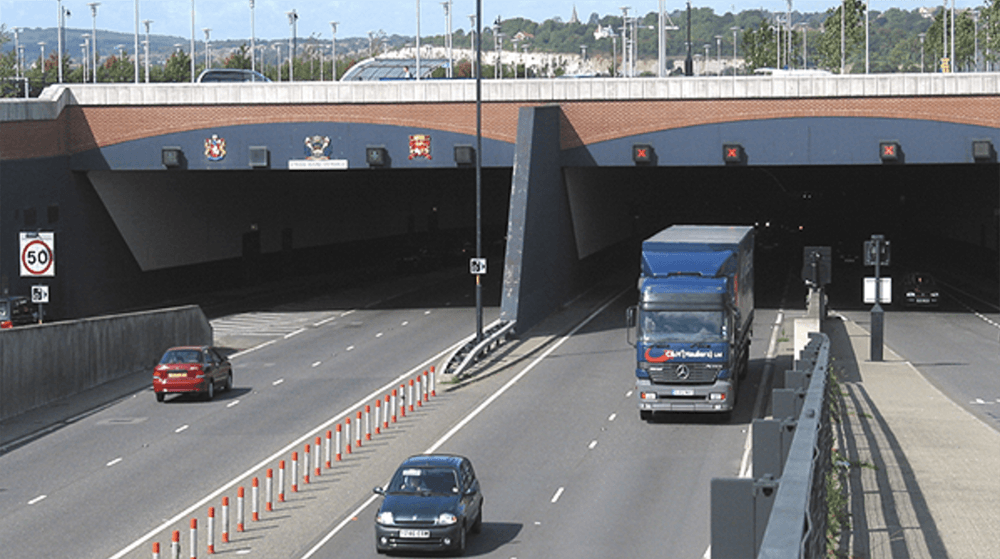
The Medway immersed-tube tunnel forms the third crossing of the River Medway near Chatham in north Kent. The tunnel was constructed as part of Kent County Council’s Medway Towns Northern Relief Road. A design and construct contract for the tunnel and 1200 m of approach structures was awarded to a joint venture between Tarmac and HBM. Mott MacDonald undertook the design for the joint venture and provided engineering support during construction. The dewatering works for the casting basin were carried out by WJ Groundwater Ltd on a design and build basis under contract to the joint venture. This paper describes the ground investigation and geology and provides some details of the design and construction of the approach embankments to the tunnel and the casting basin used for the construction of the immersed-tube tunnel units.
Ground Investigation
A number of ground investigations have been carried out in the area. These include investigations for the naval-base redevelopment as well as ground investigations for the immersed-tube tunnel (between 1986 and 1989). These investigations were used for preliminary design.
An additional investigation was carried out in 1991 to supplement the existing data and to establish accurately the soil sequence and its variations along the proposed alignment. The additional investigation included boreholes and static cone penetration testing as well as laboratory testing of the materials encountered. Fig. l(a) summarizes all geotechnical investigations used for the project. A section showing the permanent geotechnical structures along the road alignment is shown in Fig. l(b).
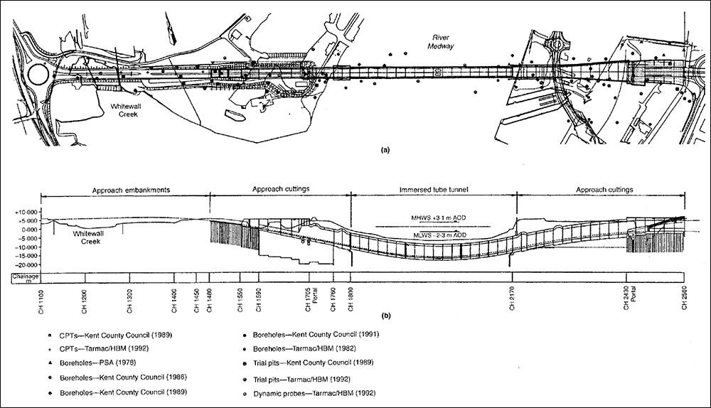
Figure 1: (a) Summary of geotechnical investigations. (b) long section showing the permanent geotechnical structures.
Geology and Ground Conditions
The site occupies the southern portion of the London Basin. The local geology is dominated by the River Medway, which ha s incised a channel in the chalk. The channel is now partly in:filled with geologically recent alluvial materials. The geological sequence is made ground overlying a variable thickness of alluvial soft clays and silt, which in turn overlies alluvial sands and gravels and then the Upper Chalk.
The made ground was up to 3 m deep and was found to be variable with materials ranging from loose to medium dense gravels, brick rubble and wood fragments to organic clay. The results of standard penetration tests varied between 2 and 25, confirming the variability.
The cohesive material in the made ground was generally stiffer than the alluvium.
The alluvial materials varied greatly in thickness owing to the depth of incision of local channels into the chalk. The granular alluvium was generally in a medium dense state and was found to thin out considerably in some areas. The cohesive material had undrained shear strengths between 10 and 30 kN/ m2 with an average moisture content of 50% and a liquid limit of 80%, and was found to have high organic contents in places .
The geotechnical parameters in the design are shown in Table 1.
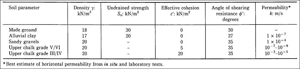
Table 1. Summary of geotechnical properties used for design.
Geotechnical Structures
The geotechnical structures can be divided into several zones (Fig. l(b)):
- the approach embankments and piled sections on the western approach
- the tunnel
- the casting basin on the eastern side , which was used to form the eastern approach to the tunnel.
Two of these structures , the approach embankments and the casting bas in , formed the major geotechnical challenges and are discussed further below.
Whitewall Creek Embankment
The western approach embankments had to cross the Whitewall Creek , which is within the tidal zone of the Medway and is covered by water twice a day. The clay at the base of the creek is very soft and has a maximum depth of approximately 6 m. Design calculations showed that the stability of the embankment (maximum height of 7 m) would be marginal during the construction stages.
The preliminary design was based on the most probable geotechnical parameters and allowed for a factor of safety of 1·3. However, given the limited amount of site investigation within the creek it was decided to use an observational approach for each of the two lift stages. A critical measure of stability for such structures is the lateral movements at the toe. Owing to the limited depth of soft clay the empirical relationships typically used for the prediction of lateral movements were not appropriate. A series of numerical analyses was therefore carried out to predict lateral movements and assess the sensitivity of the parameter values selected . The results of the analyses assisted in the assessment of the risks and enabled trigger levels to be established for acceptable construction deformations.
The finite-element mesh is shown in Fig . 2. A fully coupled consolidation analysis was carried out representing the soft clay with the modified Cam-clay constitutive model which allowed a realistic gain in the undrained shear strength during consolidation. The durations of the lift and consolidation stages were defined in the preliminary design as follows:
(a) construction of bund/installation of drains / fill to + 5·2 m OD: 4 months
(b) consolidation period: 9 months
(c) second-stage filling to + 7·85 m: 3 months
(d) second consolidation period: 15 months.
With the help of finite-element analysis results, a rate of lateral movement at the toe was defined after which contingency measures would be implemented. The observational method developed was as follows:
(a) Construction. Carry out filling at a rate of not more than 1 m per week and not more than 0·5 m per day, instrumentation to be read daily.
(b) Trigger level. Apply contingency measures if the rate of lateral movement at the toe exceeds 40 mm per week (6 mm per day), instrumentation data to be assessed daily.
(c) Contingency. Stop filling immediately and unload if movements continue.
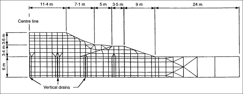
Figure 2: Finite element mesh and parameters used for the analysis of the Whitewall Creek embankment.
The deformation measurement consisted of inclinometers, extensometers, surface observation points read for both vertical and lateral movement and settlement plates. The best quality data were obtained from the inclinometers and extensometers, which were backed up by the observation points and settlement plates. Unfortunately, of the six extensometers initially installed, three were lost during the hydraulic filling and two during subsequent filling. However, one extensometer functioned throughout the construction and was used in the comparison with the numerical results. This extensometer, together with surface levelling and inclinometer monitoring , was sufficient for monitoring deformation.
Four pneumatic piezometers were installed in the soft clay below the bund to monitor stability during filling. The measurements were intended to back up the lateral movement monitoring, but in the event were very difficult to interpret. In addition, because of major dewatering for the nearby casting basin the equilibrium pore pressure in the soft clay was not accurately known. The piezometers ceased working during the second liftowing to excessive lateral movement. The piezometers were not replaced , as deformation monitoring provided sufficient information to allow the observational method to be applied.
All instrument at ion was read daily during construction. The frequency of monitor ing was gradually reduced during the consolidation stages to a minimum level of once per month.
Comparison of Observed and Predicted Behaviour
The finite-element predictions and observed behaviour are compared for the settlement at extensometer 123R and for the maximum lateral movement below the toe in Figs 3 and 4, respectively. The trigger level for the lateral movement was not exceeded during construction. While the durations of the loading and consolidation stages varied slightly between the predict ion and construction, the comparison of both lateral and vertical movements is reasonable for the construction periods and the first consolidation stage. During the second consolidation stage (February 1994 to May 1995) the observed rate of movement was greater than predicted.
This may have been due to creep, which was not accounted for in the numerical analysis. Surcharge loading was removed in April 1995 and the vert ical movement thereafter was small.
Use of the observational method allowed the embankment to be constructed in the mo s t economic al way. The success of the observational method was due to accurate initial prediction of behaviour , diligent data collection on site and flexibility in the construction process.
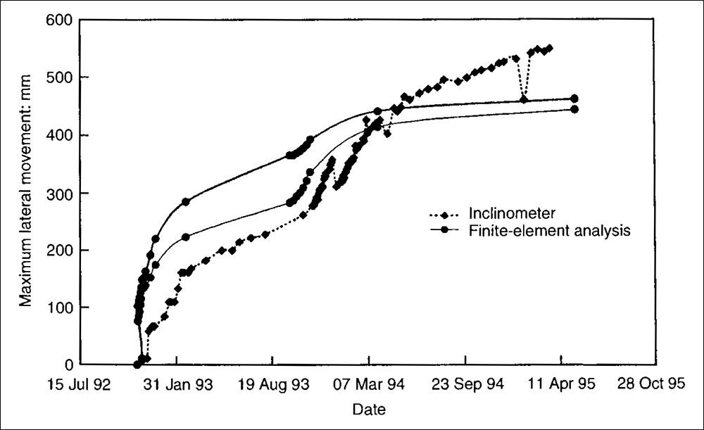
Figure 3: Observed and predicted settlement below the shoulder of the Whitewall Creek embankment.
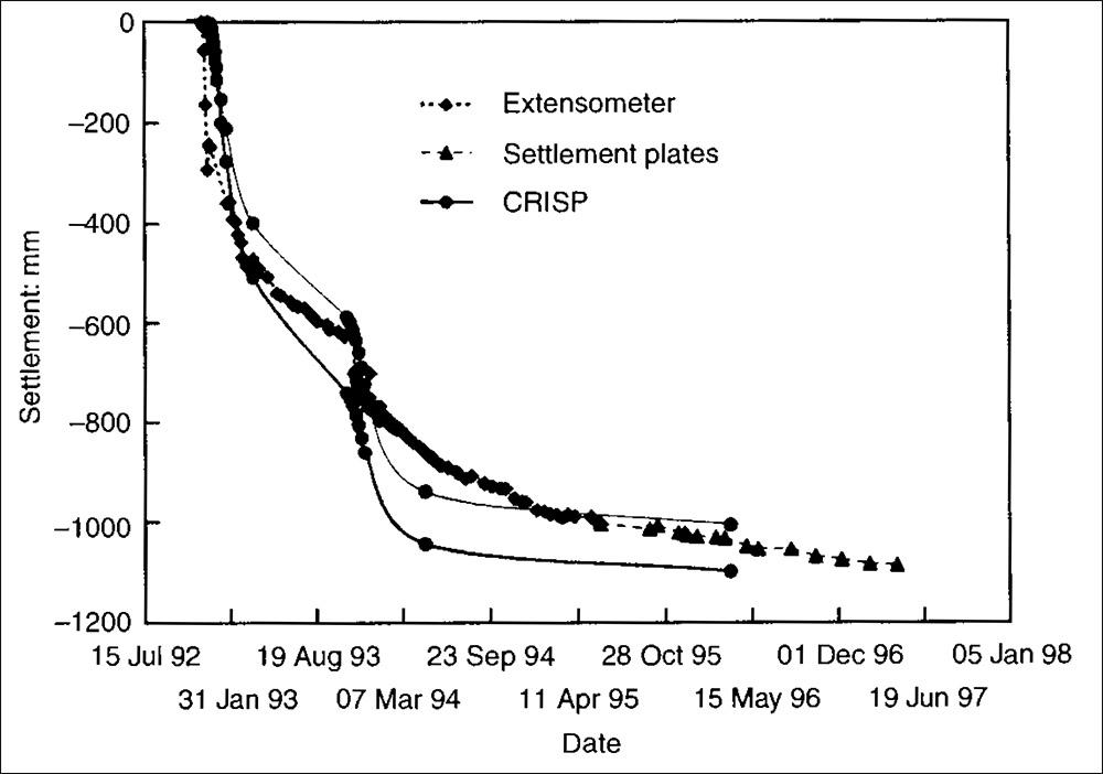
Figure 4: Observed and predicted lateral movement at the toe of the Whitehall Creek embankment.
The Casting Basin
The three tunnel elements for the immersed-tube tunnel were constructed in a casting basin (Fig. 5) on the east bank of the river. Following the flooding of the casting basin and float -out of the tunnel elements, the casting basin was redrained and used to accommodate the eastern approach structure.
The size of the casting basin, the duration for which it would be dewatered, the geology and the proximity of historically important structures made the casting basin the most critical geotechnic al structure. The incorporation of the casting basin into the permanent approach works had major economic advantages as the tunnel units were constructed partially ‘on line’.
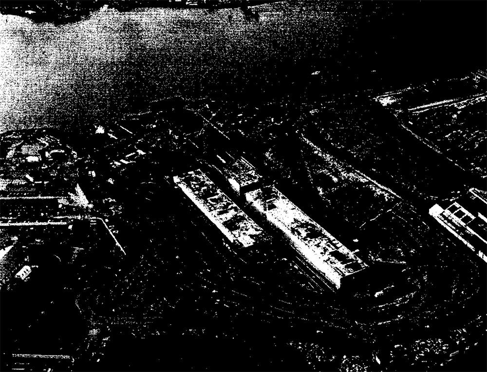
Figure 5: Construction of tunnel units in the casting basin.
Slope Design
The location of the casting basin was determined by the available site geometry and the economic assessment of a large number (more than ten) of alternative options. Casting basin sites on both the east and the west bank of the Medway were considered, together with one off-site option and one ‘in line’ option involving unit s cast on both banks. A combination of open-cut excavations, sheet pile, diaphragm, pinapile, secant and combipile options was considered to enable the required excavation area to be provided within the site area avail able.
It was evident from site excavation trials and earl y site investigation results that excavation slopes in the alluvial clays would need to be between 1 vertical to 3 horizontal and 1 vertical to 4 horizontal. It was also evident from an earl y stage that a retaining wall at either the crest or the toe of the excavation would be required to enable the casting-basin footprint to be constructed within the available site area . The casting-basin excavation was also required to tie in with the temporary cofferdams at the interface between the tunnel units and the in situ works. The major constraints to the casting-basin layout were the location of potential obstructions at a slipway location 50 m south of the tunnel portal and a substantial listed building just north of the road alignment (Fig. 6).
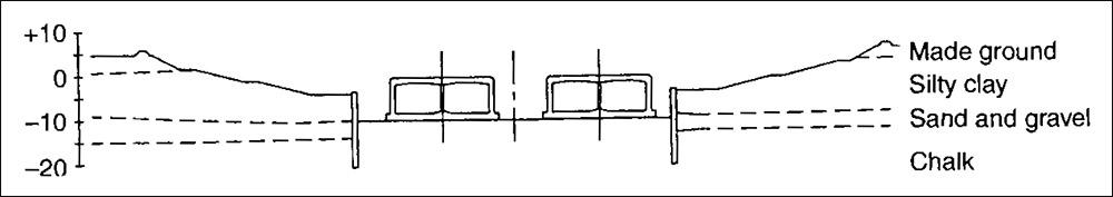
Figure 7: Design of casting basin slope.
Hydrostatic groundwater levels were taken at or close to the ground surface to approximate rapid-drawdown conditions. Piezo metric pressures within the gravel horizon were varied in order to determine pore pressure limits for stability. It should be noted that once the tunnel units were constructed , the casting basin was to be flooded for float-out and then redrained to enable the approach works to be constructed. The excavation slopes were as follows:
(a) made ground: 1 vertical to 2 horizontal
(b) alluvial clays: range 1 vertical to 2·5 horizontal to 1 vertical to 4 horizontal (depending on location and soil conditions)
(c) chalk: 1 vertical to 2 horizontal.
The casting basin was fully instrumented with piezometers and in clinometers and a positive management system was adopted to enable excavation slopes, the retaining wall and groundwater levels to be monitored during the works.
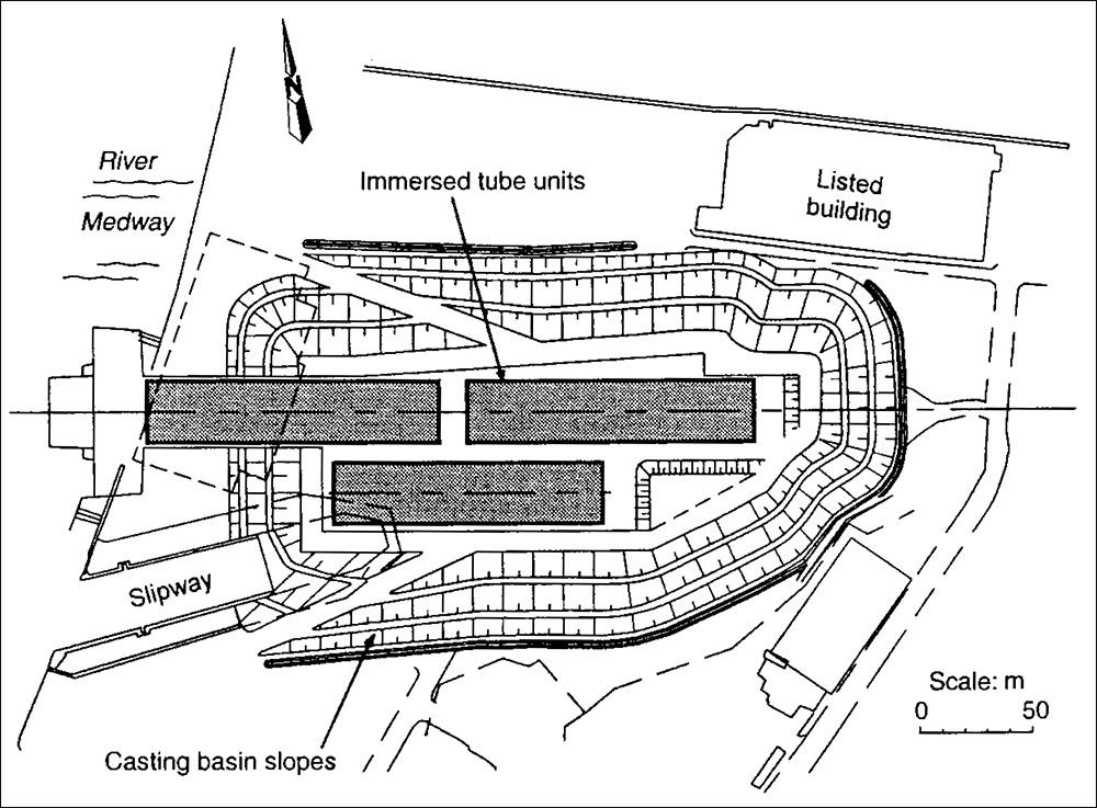
Figure 6: Casting basin layout required showing location of the portal, slipway and listed building.
A 15 m deep excavation was required to enable float-out of the tunnel units and their passage through the portal cofferdams. It was decided to cast three units , each 127 m long. This minimized the number of construction joint s in the submerged section of the tunnel. The chosen design combined an open excavation with a 6 m high retaining wall at its toe as shown in Fig. 7. Soil data from additional site investigations enabled a three-dimensional mod el of the anticipated soil conditions to be plotted. Slope analyses were carried out using circular (Bishop) and non-circular analyses for both long-term and short-term parameters . A minimum factor of safety of 1·3 was adopted in all cases in view of the serious risks to the project in the event of a slope or retaining-wall failure, which could have physically dislodged or damaged the tunnel units.
Casting Basin Dewatering
The layout of the casting basin is shown in Fig. 6. The casting bas in had battered slopes to -4·5 m OD and a cantilever retaining wall allowing excavation to – 10·5m OD. The narrow section of the casting bas in, connecting it to the river, was supported by a combi-pile propped retaining wall an d the river closure was achieved with three coffer dam cells. The maximum required excavation depth was to -14·5 m OD for the reaction slab and sill adjacent to the river.
Hydrogeological conditions. The hydro geological conditions are summarized in Fig . 8. The Upper Chalk is the principal regional aquifer and is widely use d for water supply, although not in the immediate vicinity of the site because the water is brackish. There were two licensed abstractors within 1·5km of the site, but the nearest public supply was 4 km away. The river gravels and the chalk were in direct hydraulic connection, with the superficial allu-vial clays acting as a confining layer. The alluvial clays also provided a lining in the base of the river, which greatly reduced the hydraulic connection between the river and the gravel / chalk aquifer. Monitoring of groundwater levels on the site indicated a stand ing groundwater level of 0·5 to 1·0 m OD with tidal fluctuations accounting for the 0·5 m difference in level.
Design of dewatering scheme: Draw downs of at least 12 m (l ·0 to -11 ·0 m OD) were clearly required in the gravel and chalk aquifer to provide dry conditions and base stability. At least 7 m (l·0 to -6-0 m OD) of drawdown was also required below the batters to provide slope stability.
Estimates of the seepage flow s to the casting-basin excavation were based on the following assumptions.
- The alluvial clay provided an upper con fining layer of negligible permeability.
- The gravel and chalk were in hydraulic continuity with a transmissivity in the range 2 x 10- 3 to 1 x 10- 2 m 2/s .
- The distance of influence was estimated to be 400 to 900 m.
- The standing groundwater level was taken to be up to + 2 m OD.
- Any beneficial effect of the combi-wall providing a cut -off was ignored.
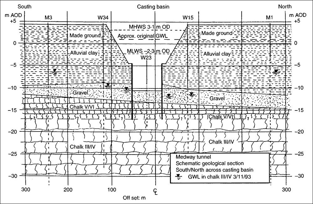
Figure 8: Summary of hydrogeological conditions.
Three methods of analysis were adopted: two-dimensional plane flow, radial flow to a single large well and superposition using test data from previous dewatering works carried out in 1988 for a lock located 500 m north of the casting basin. The result s of the steady-state confined-aquifer analysis are summarized in Table 2, which shows estimated flows in the range 108 to 3531/s. In order to control these flows a scheme was proposed comprising 27 wells (19 external and eight internal) fitted with pumps of capacity 12 1/s , giving a total system capacity of approximately 3241/ s . The wells were installed to – 20 to – 25 m OD and were designed to extract water from both the gravel and the chalk. A phased approach to the installation was adopted, with test pumping data collected from the initial wells use d to refine the design of the scheme.
Performance of the dewatering system: Monitoring of the dewatering works was carried out us ing an array of 20 piezometers in the immediate vicinity of the casting basin and eight remote piezometers located 150 to 200 m from the edge of the excavation. It quickly became apparent that discharge flows would be greater than predicted and the number of wells was increased from 27 to 40. The majority of the additional flow was from the landward end of the casting basin, where the chalk out cropped in the base of the excavation . Prompt analysis of the performance of the dewatering system allowed the additional wells to be installed and commissioned within the original programme. It can be seen from Fig. 9 that the recorded daily discharge flows for full draw down were between 350 and 4001/ s. The piezometer records for full drawdown are summarized on a semi logarithmic graph in Fig. 10. This plot includes data from the Environment Agency (formerly the National Rivers Authority’s) monitoring boreholes in the area and from piezometers located around the western app roach on the opposite side of the river from the casting basin. The integrity of the alluvial clay in sealing the base of the river is demonstrated by the fact that drawdown to – 5 m OD was achieved on the far bank of the ri ver, 500 to 600 m from the centre of the casting bas in. This significantly reduced the dewatering operations required for the western approach works.
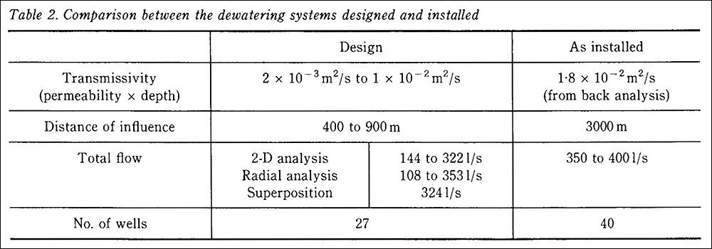
Table 2: Comparison between the dewatering systems designed and installed.
Dredging Works and Casting Basin Flooding
While the tunnel elements were under construction in the casting basin, dredging works were carried out in the river bed to form the trench for the immersed tunnel. The dredged trench formation level was -12 to -19 m OD, which penetrated some 5m int o the chalk. There was some concern that the trench excavation would provide a hydraulic connection between the river and the gravel/ chalk aquifer, adversely affecting the drawdown around the casting basin and allowing a direct flow path for saline water from the river int drawdown or the water quality. It is presumed that the heavy silty load in the river provided rapid plugging of the exposed gravel and chalk, thereby maintaining the integrity of the seal.
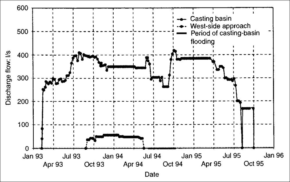
Figure 9: Measured discharge from the casting basin dewatering system.
The casting basin was to be flooded with river water to allow the float-out of the tunnel elements. There was concern that this operation could allow saline water to enter the aquifer, extend in g the area of saline intrusion. In order to minimize this risk it was decided, in consultation with the Environment Agency, to cap the internal wells but to maintain the external system in operation. This would ensure that any saline intrusion would only take place in the immediate vicinity of the casting basin. In addition, any saline intrusion which did take place would be largely removed by the dewatering system when the casting basin was redrained to allow construction of the app roach structure. This strategy proved successful. As so on as the casting bas in was flooded, the salinity of the discharge water rose appreciably, indicating that significant infiltration through the base of the casting basin was ta kin g place. This was also confirmed by the fact that drawdown levels rapidly recovered up to about O to -1 m OD even though discharge flows were maintained at 250 to 3001/s (seeFig. 9). At the end of the float-out period, when the casting basin was redrained, the discharge water recovered to pre flooding quality levels within a couple of months.
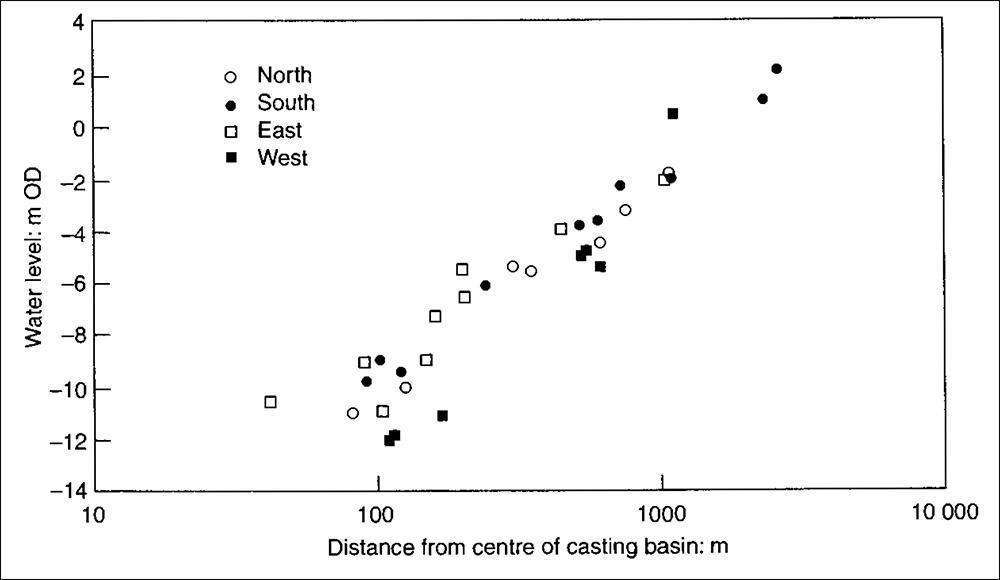
Figure 10: Piezometer for full drawdown of casting basin.
Conclusion
The geology and hydrogeological conditions at the site posed several challenges to the design and construction team. Through tho rough investigation and interpretation and careful design and construction, the potential difficulties were avoided and the challenging ground conditions were us ed to maximum advantage.
The most significant geotechnical structure was the casting basin. This was a 15 m deep excavation used to construct the tunnel sections , which was then incorporated into the permanent works.
The casting basin required careful design and construction to ensure that the structure remained s table and that no significant damage was caused to the adjacent historic structures.
Observational methods were used for the approach embankments, where stability of the structure could not be guaranteed, and for the casting -basin dewatering. On-site monitoring was carried out and compared with predictions to ensure successful construction.
Coordination between the design and site teams allowed safe, efficient and economic construction.
Acknowledgements & References
References
- PECK R. B. Advantages and limitations of the observational method in applied soil mechanics. Geotechnique, 1969, 19 , No. 2, 171- 187.
- KRUIZENGA H. and W EEKS C. R. Medway Tunnel detailed design. Tunnelling ’94. Chapman & Hall, London, 1994, 579- 601.
- R USSELL D. Discussion of the observational method in geotechnical engineering. In The Observation al Method in Geotechnical Engineer in g. Thomas Telford, London, 1996, 179-185.
Link
To read the full, original published paper, please click on the link below: