In-Tunnel Dewatering for a Cross Passage in London
WJ Whitepaper
Abstract
The Crossrail project in London comprises twin TBM driven railway tunnels. The scheme includes several short cross link tunnels between the TBM drives to house switch gear, sumps and for access. Cross passage CP6 is 14 m long and includes a central sump. This cross passage is at 48 m depth and lies within the Lambeth Group soils present immediately below the London Clay. The Lambeth Group soils are predominantly cohesive but include intermittent, water bearing channel sands with excess pore pressures of 1 to 2 bar. The cross passages are constructed using SGI rings with reinforced concrete collars.
Temporary ground support during excavation was provided using timber headings requiring dry, stable face conditions. Probe drilling undertaken from the running tunnels in advance of the excavation of CP6 identified the presence of water bearing granular horizons, above, within and below the tunnel and sump horizon. The probe holes were completed as wellpoints or piezometers with the borehole logs used to update the ground model. The ground model was essential for the development of a temporary in-tunnel dewatering scheme to target the water bearing horizons and facilitate cross passage construction in dry stable conditions.
AUTHORS:
T.O.L. Roberts (WJ), E. Linde (OTB) and M. Sutton (WJ)
- WJ Groundwater Ltd, London, UK
- OTB Engineering, London, UK
DATE:
November 2015
SUMMARY:
This paper describes the development and implementation of an in-tunnel Wellpoint and ejectors scheme for a cross passage link and central sump between two TBM running tunnels.
1. Introduction
Crossrail is a major new east-west underground rail link through central London. The main 6.2 m diameter running tunnels have been driven by TBM with most of the underground stations, cross over caverns and link tunnels constructed using sprayed concrete lining (SCL) techniques or Spheroidal Graphite Iron (SGI) rings. In central London the Crossrail works extend up to approximately 50 m depth in order to avoid London’s extensive existing underground railway and services network.
Much of the existing shallower railways and the western section of Crossrail have been constructed in the stiff cohesive over-consolidated London Clay.
However the London Clay thins to the east so that the Crossrail tunnel horizon reaches to the Lambeth Group soils present below. The Lambeth Group strata in central London comprise a succession of predominantly cohesive soils but with intermittent water bearing non-cohesive channel sands present. The challenges that these soils present to tunnelling were first encountered by Marc Brunel and his son Isambard Brunel during the construction of the first tunnel below a navigable river, The Thames, in 1825 to 1843, see Skempton and Chrimes 1994.
This paper is concerned with the dewatering and depressurisation measures required for Crossrail tunnel CP6 which comprises a 14m long cross passage with central sump linking the two TBM tunnels together with catch pits and linking drains, See Photos 1 and 2.
The ground conditions are described together with the probe drilling strategy used to investigate conditions at the tunnel horizon. Information from the initial probe drilling was used to develop and refine the ground model which then provided the design basis for the dewatering and depressurisation strategy. The purpose of the temporary dewatering and depressurisation works was to reduce pore pressures to zero or below to allow construction of the cross passage using open face excavation and timber heading support techniques.
Careful consideration was given to the possibility of obtaining surface access for probe drilling and depressurisation. However this was not considered viable given the depth of the works and the congested urban environment above.
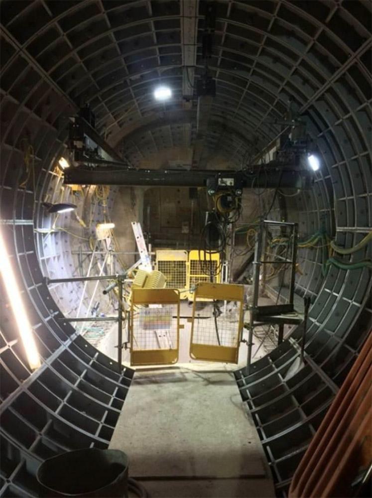
Photo 1. Completed cross passage
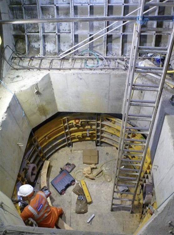
Photo 2. Completed sump
2. Ground Conditions
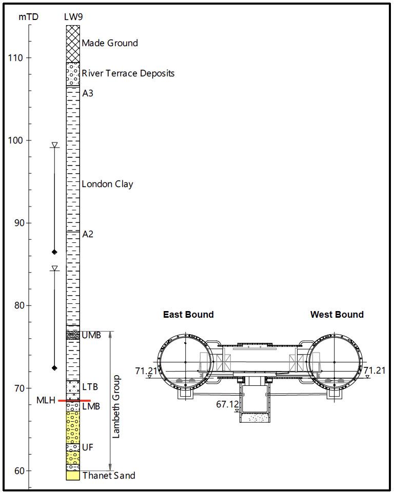
Figure 1: CP6 cross section showing anticipated ground profile.
The general succession of strata in central London is well known, Sumbler 1996. There was also a site investigation borehole, LW9, installed just 11 m from CP6 which proved the interface levels and provided the initial ground model, see Figure 1.
Borehole LW9 showed that CP6 would be constructed in the upper Lambeth Group with the central sump extending down to about 1 m below the Mid-Lambeth Hiatus (MLH). The pore pressure profile in the vicinity of CP6 is shown in Figure 2. This is based on monitoring data from piezometers in the vicinity (including at LW9) recorded intermittently between 1992 and 2010, and is typical of the prevailing under drained pore pressure profile present in central London. Over abstraction from the chalk between about 1850 and 1965 has reduced groundwater levels in the Lower Aquifer below London, comprising the Lambeth Group Upnor Formation, Thanet Sand and Chalk. Groundwater levels had started to rise between 1965 and 1990 but are now maintained by pumping from wells across London to protect the extensive deep infrastructure which was constructed after groundwater levels had been lowered, Environment Agency 2015.
Groundwater levels in the Terrace Gravels (Upper Aquifer) above the London Clay are largely unchanged. The London Clay and Lambeth Group clays act as a dividing layer between the Upper and Lower Aquifers. Figure 2 shows that the non-cohesive sand and gravel horizons which are intermittently present, mainly in the upper Lambeth Group, have not been fully drained and form an Intermediate Aquifer.
The Crossrail site investigation works have shown that the MLH is the approximate boundary with any non-cohesive horizons below this level generally reflecting groundwater levels in the Lower Aquifer whilst those above can exhibit elevated pore pressure between those in the Upper and Lower Aquifer.
It is a common misconception that the elevated pore pressures in the Lambeth Group are relic and once dissipated will not recover. This may be partly true in so far as the highest pressures, those above about 100 kPa, have proved elusive to reproducible measurement. Pressures below this do tend to recover when pumping stops. Whilst the vertical permeability of the lower Lambeth Group clays is clearly very low (probably <10-9 m/s) it seems highly unlikely that elevated relic pore pressures could be sustained over more than 100 years without some form of seepage inflow which exceeds the downward leakage outflow.
Possible sources of seepage inflow include; leakage flow through the London Clay possibly via fissures; seepage via ungrouted boreholes; or horizontal seepage through the channel sands from areas of higher groundwater level which may be several kilometres away. Skipper et al 2015 has reported that chemical analysis data indicates that the dominant source of inflow is horizontal seepage through the channel sands.
3. Dewatering Requirements
Depressurisation was only required for CP6 excavation where both excess pore pressures and non-cohesive soils were present at or within approximately 4 m of the tunnel and shaft horizon (to either side, above and below). Beyond this there was sufficient clay cover to provide the necessary temporary face stability during excavation. Whilst significant excess pore pressures are indicated to be present in borehole LW9, just 11 m away, the borehole log did not identify non-cohesive horizons in the relevant zone. This implied that depressurisation above the MLH may not be needed for construction of CP6.
However the intermittent nature of the channel sands and associated serious risk to the tunnel stability meant that probe drilling was necessary to confirm conditions. The water levels in the lower aquifer below the MLH were below the invert of the cross passage, but above the sump formation level. Therefore localised dewatering was required for the sump excavation. The required pore pressure profile during CP6 excavation is shown in Figure 2.
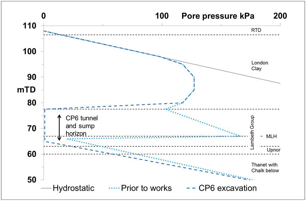
Figure 2: Pore pressure profile
4. Probe Drilling Strategy
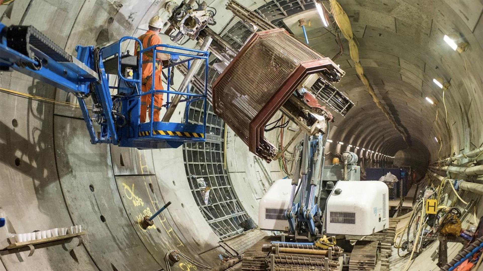
The purpose of the probe drilling was to confirm the required 4 m thickness of cohesive soils around the cross passage and sump excavation. The probe holes were completed as wellpoints which could be used to monitor pore pressures or they could be pumped on if depressurisation was required. In the event of a probe hole encountering water bearing channel sands it was essential to be able to seal the bore to prevent excessive groundwater inflow and associated ground loss. In order to ensure that this could always be achieved all probe holes were undertaken through a preinstalled threaded insert grouted into the tunnel lining. This also provided a means for permanently sealing each bore on completion of the works. Drilling was undertaken using compact rotary drilling rigs with a high degree of articulation and specially adapted for auger drilling and well installation in a tunnel environment, see Photo 3.
A range of drilling techniques was available which provided progressively higher levels of bore control as follows:
- Auger drilling: This provides good soils information for bore logging in cohesive soils or non-water bearing granular soils but offers little bore control if sands are encountered at high pressure. Pre-agreed strategies were developed for this eventuality including; leaving the auger in the bore; or withdrawing and sealing the threaded insert.
- Drill through valve: This could be connected to the threaded insert and would allow the bore to be sealed with a valve as soon as the drill string was removed.
- Cased drilling through a preventer (stuffing box) and drill through valve both fixed to the threaded insert: This provides full control of the borehole annulus during drilling.
- As above but with lost bit drilling: This provides complete control of the bore throughout drilling and subsequent well or piezometer installation.
Where sand horizons are encountered the speed of installation, bore length and quality of information on the ground conditions all reduce with increased pore pressures and corresponding increased levels of bore control. Completing the bores as wellpoints allowed immediate commencement of monitoring and depressurisation where sand channels were encountered. This was essential so that reduced bore control measures could be used, which was necessary to generate good quality ground profile information.
The initial probe drilling array comprised 24 No. bores to either side of CP6 and around each catch pit. These ranged in length from 4 to 14 m and were designed to check conditions above, to either side and below CP6. In addition an array of 6 No. inclined ejector wells were installed to target the Upnor Formation below the sump which was already known to require depressurisation.

Photo 3. Upwad drilling for probing and well installation
5. Development of the Ground Model
As the probe drilling progressed it quickly became apparent that significant water bearing granular soils were present in the tunnel crown and invert and, as expected, at the base of the sump. The protruding wellpoint casings were used to survey the ‘as built’ borehole alignment and this information together with the probe hole logs was used to build up a ground model which was then further refined as more information became available. The final ground model along the centre line of the CP6 is shown in Figure 3.
It can be seen that there was an extensive sand channel in the crown of the east bound tunnel extending down to the axis of the west bound tunnel. CP6 invert and the TBM tunnel catch pits were in the laminated beds which were non-cohesive plus the sump extended down into the sands of the Upnor formation which are in direct hydraulic continuity with the Thanet Sand below. These individual sand horizons were not in direct hydraulic connection with one another which meant that it was important to identify the interface levels. This is because, to be fully effective at achieving the maximum drawdowns, the well installations need to be screened across the interface and where possible should target interface low points.
The probe drilling, wellpoint installation, monitoring, pumping and refinement of the ground model were an integrated process which continued until the pore pressures had been fully controlled so that construction of CP6 could commence.
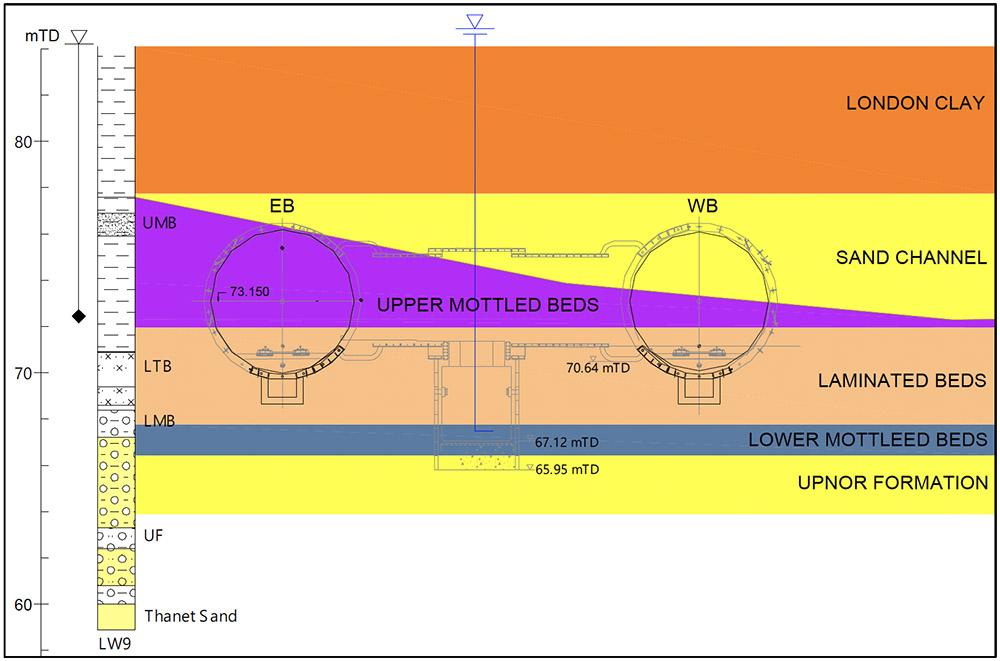
Figure 3: Final Ground Model
6. Completed Dewatering Scheme
The completed well array is shown in plan and section in Figures 6 and 7. The 12 No. upwards installations encountered pressures of up to 0.6 bar initially. This was reduced to zero, particularly once the lower level pumping commenced. The upper wellpoints were pumped with a vacuum pump but this was largely to manage the groundwater ingress to the tunnel and it seems likely that passive relief would have been sufficient. The combined inflow from the high level wellpoints was <1 l/s.
The channel sands and the laminated beds were effectively dewatered together using the 44 No. shallow downward wellpoint array installed in both tunnels. The highest flows were to the south of the west bound tunnel where the channel sand horizon appeared to be thicker. Pore pressures in these horizons were drawn down from approximately 86 mTD to 71 mTD. The combined flow rate of the downward wellpoints was 3 l/s.
The Upnor Formation present at the base of the sump was dewatered using an array of 6 No. ejector wells installed from the east bound tunnel. Ejectors were chosen because the drawdown depth was over 6 m which is beyond the suction lift of a wellpoint system, particularly in fine soils. Groundwater levels in the Upnor Formation were reduced from from 68 mTD to 65.6 mTD. The combined abstraction flow from the ejector wells was <1l/s.
The pump set-up in one of the TBM running tunnel adjacent to CP6 is shown in Photo 4.
The monitoring data collected from the surface piezometer LW9 and several in-tunnel piezometers is given in Figure 6. LW9 shows a clear response to the start of drilling and the recovery is evident 4 months later when the cross passage was completed and the dewatering system decommissioned. The full response is not evident from the in-tunnel instruments because these were commissioned sometime after pumping commenced and were decommissioned at the same time as the wellpoints. The purpose of the in-tunnel monitoring was to confirm the ongoing effectiveness of the dewatering operation and to provide an in-tunnel alarm system in the event of any recovery in groundwater levels during the excavation works.
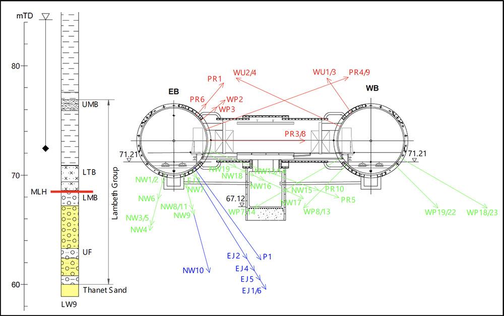
Figure 4: Section of final well array
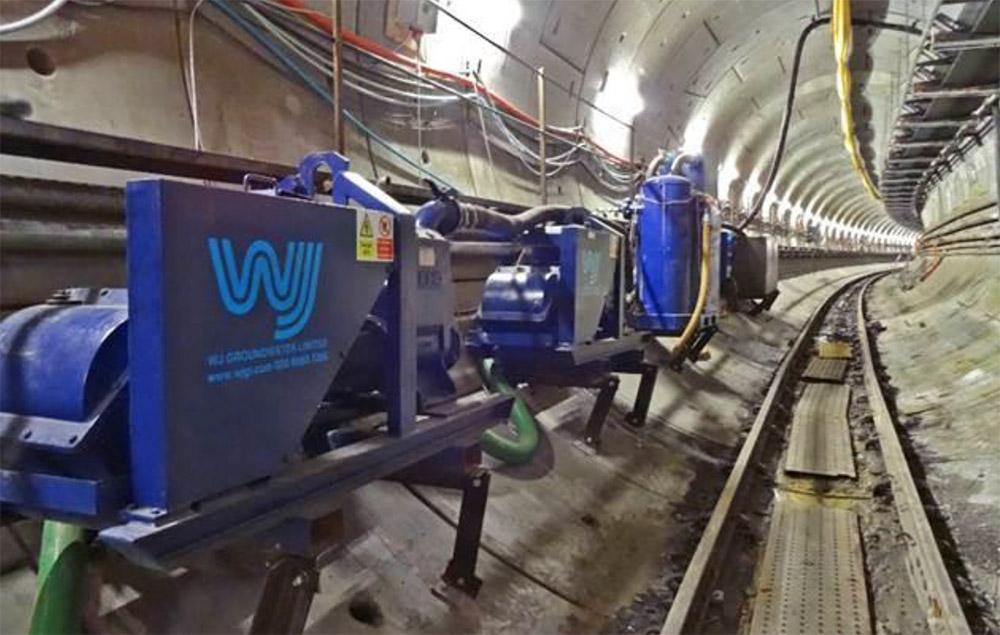
Photo 4: Pumping set-up
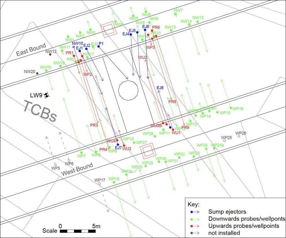
Figure 5: Plan of borehole installations
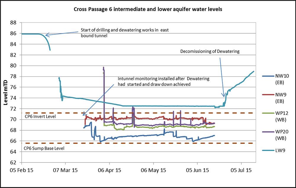
Figure 6: Monitoring data
7. Conclusions
These works demonstrate the challenges faced when dealing with groundwater in open face tunnels in the Lambeth Group. The nearby borehole log provided little indication of the scale of the dewatering requirements. Preliminary probing through the tunnel segment grout holes provided some early warning that conditions might not be as benign as initially thought. This ensured that pumping plant was mobilised at the same time as the probe drilling commenced. Central to the whole process was the continuous development and refinement of the ground model because this guided the subsequent borehole installation angles, lengths and completion details.
The facility to pump immediately following installation, combined with real time data logger monitoring, allowed an immediate assessment of the effectiveness of the installed scheme. Also the continuous reduction in pressures reduced the bore control measures required, improving the quality of logging and well installation in subsequent bores.
The dry channel sands found in the crown and dry laminated beds found at invert are shown in Photo 5.
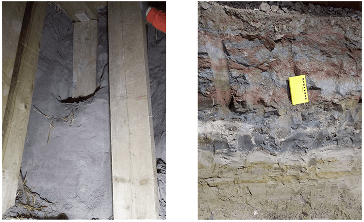
Photo 5: Dry non-cohesive soils encountered during excavation of CP6.
LEFT: Channel sands in the crown. RIGHT: Laminated beds at invert.
Acknowledgements & References
Acknowledgements
Many individuals contributed to the success of this project and the authors would like to acknowledge the project client Crossrail, the permanent works designer Atkins and Arup, the main contractor DSJV (Dragados Sisk Joint Venture) the temporary works designer OTB Engineering and the dewatering subcontractor WJ Groundwater.
References
Environment Agency 2015. Management of the London Basin Chalk Aquifer: Status Report, Environment Agency, London.
Skempton and Chrimes 1994. Thames Tunnel: geology, site investigation and geotechnical problems. A W Skempton and M M Chrimes. Géotechnique, Volume 44, Issue 2, 01 June 1994, pages 191 –216. ICE London.
Skipper et al 2015. The Lambeth Group in the Crossrail Project of London, UK – the geological model. J A Skipper, H E Scholes, U Lawrence, M Packer and C O Menkiti. Proceedings of the XVIECSMGE Geotechnical Engineering for Infrastructure and Development, 2015 doi:10.1680/ecsmge.60678.
Sumbler 1996. British Regional Geology: London and the Thames Valley, 4th Edition. M G Sumbler, 1996. London: HMSO British Geological Survey.
Link
To read the full, original published paper, please click on the link below: