Soil Characterisation and Construction of Deep Excavations in High Permeability Gravels in Cork, Ireland
WJ Whitepaper
Abstract
Ground conditions, soil characteristics and difficulties encountered in constructing deep excavations in highly permeable fluvioglacial gravels in Cork city, southern Ireland are described. The gravels are medium dense to dense, have low sand content and high permeability.
Significant pumping effort is required to dewater excavations. Settlements of adjacent buildings due to under-drainage of alluvial soils, overlying the gravels, are of significant concern. From site investigation information ground conditions appear to be uniform with depth. However site experience suggests permeability may actually decrease significantly.
AUTHORS:
• M. Long – University College Dublin (UCD), Ireland
• T. Roberts – WJ Groundwater, UK
• M. Creed – University College Cork (UCC), Ireland
Date: 2007
Introduction
This paper describes ground conditions and difficulties encountered in constructing deep excavations in highly permeable fluvioglacial gravels in Cork city, southern Ireland. Cork is believed to have derived its name from the Gaelic “Corcach Mor Mumhan” meaning the great marsh of Munster, indicating the nature of the ground conditions. Traditionally buildings in Cork were constructed without a basement. However the recent economic boom in Ireland, the requirements for car parking and the lack of development sites has resulted in the construction of a number of basements of up to two levels (7.5 m) deep.
Of particular concern during these developments is the estimation of the permeability of the fluvioglacial gravels, the design of retaining walls and dewatering systems and the prediction of settlements of adjacent buildings due to water level draw down.
Here these issues are addressed for a number of case histories. Particular emphasis is given to the Clarion Hotel development on Lapps Quay.
Background Geology
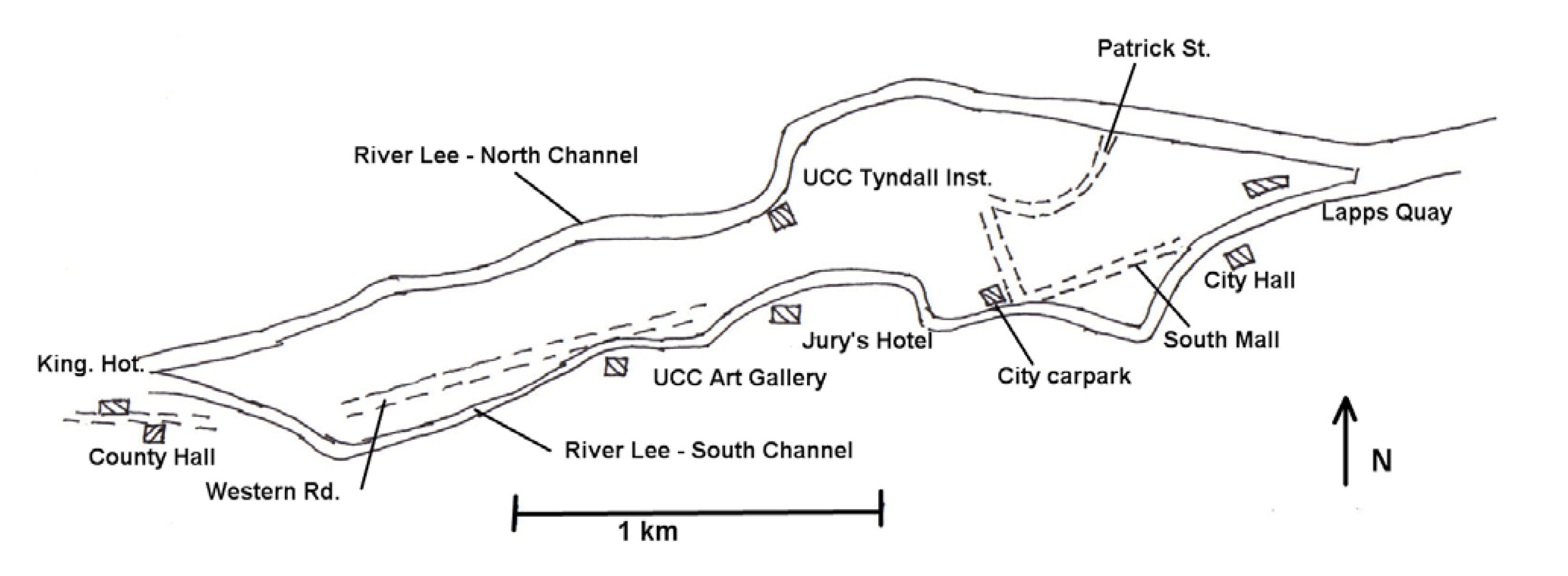
Figure 1: Location of study sites in Cork.
The River Lee, which flows through Cork city consists of two distributory channels about 400m apart. These separate about 4 km west of the beginning of the estuary and reunite near the estuary, see Figure 1. The Lee occupies a broad low-lying floodplain between 0.5 km and 0.75 km wide. Its margins are marked within Cork city by 20 m to 30 m scarps.
The Lee floodplain overlies a buried valley or “gorge” formed 15,000 years ago during the Pleistocene glaciation when sea level fell to –130 mOD and rivers cut down to the new base level (Allen and Milenic, 2003). At the end of the glaciation approximately 10,000 years ago, when the ice receded and sea level rose again, rivers infilled their valleys with sand and gravel. The Lee Buried Valley runs from Crookstown in the west to Youghal in the east, a distance of about 60 km. It is at least 60 m deep and 0.5 km to 0.75 km wide and is more or less directly underneath and in line with the central island of the city (Reilly and Sleeman, 1977, Milenic and Allen, 2002). The Buried Valley is well exposed between Classes and Garryhesta in the Ballincollig – Ovens area to the west of the city where it is being quarried for sand and gravel. Here it contains a remarkably uniform succession of gravels. However beneath Cork city the details of the stratigraphy are not clear.
Later the valley was infilled with estuarine clays, silts and peats, typically 3 m to 4 m thick. Marshes formed the final shape of the upper estuary, after the sea level steadied near its present location about 6,000 years ago. Ultimately the majority of the Cork waterways were covered over to accommodate the spacious streets required by 18th. century planners. Grand Parade, South Mall and Patrick St. appeared in this way, leaving today the North and South channels of the Lee (Whittow, 1974).
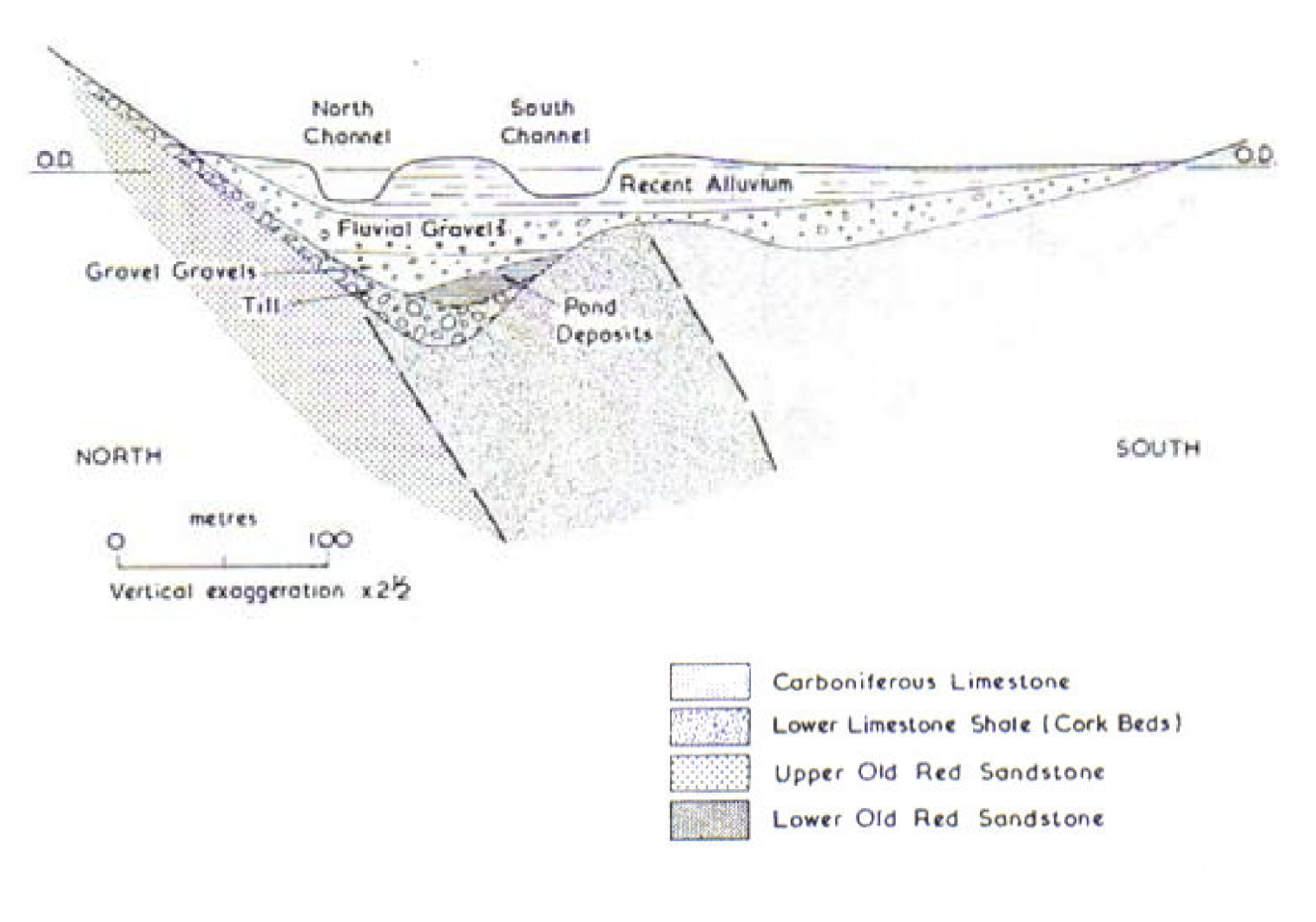
Figure 2: Diagramatic geological section across River Lee at Lapps Quay (Reilly and Sleeman, 1977).
Study Sites
Data from 8 sites are presented in this paper in order to illustrate the nature of the problem and the solutions adopted. These are listed on Table 1 and their locations are shown on Figure 1.
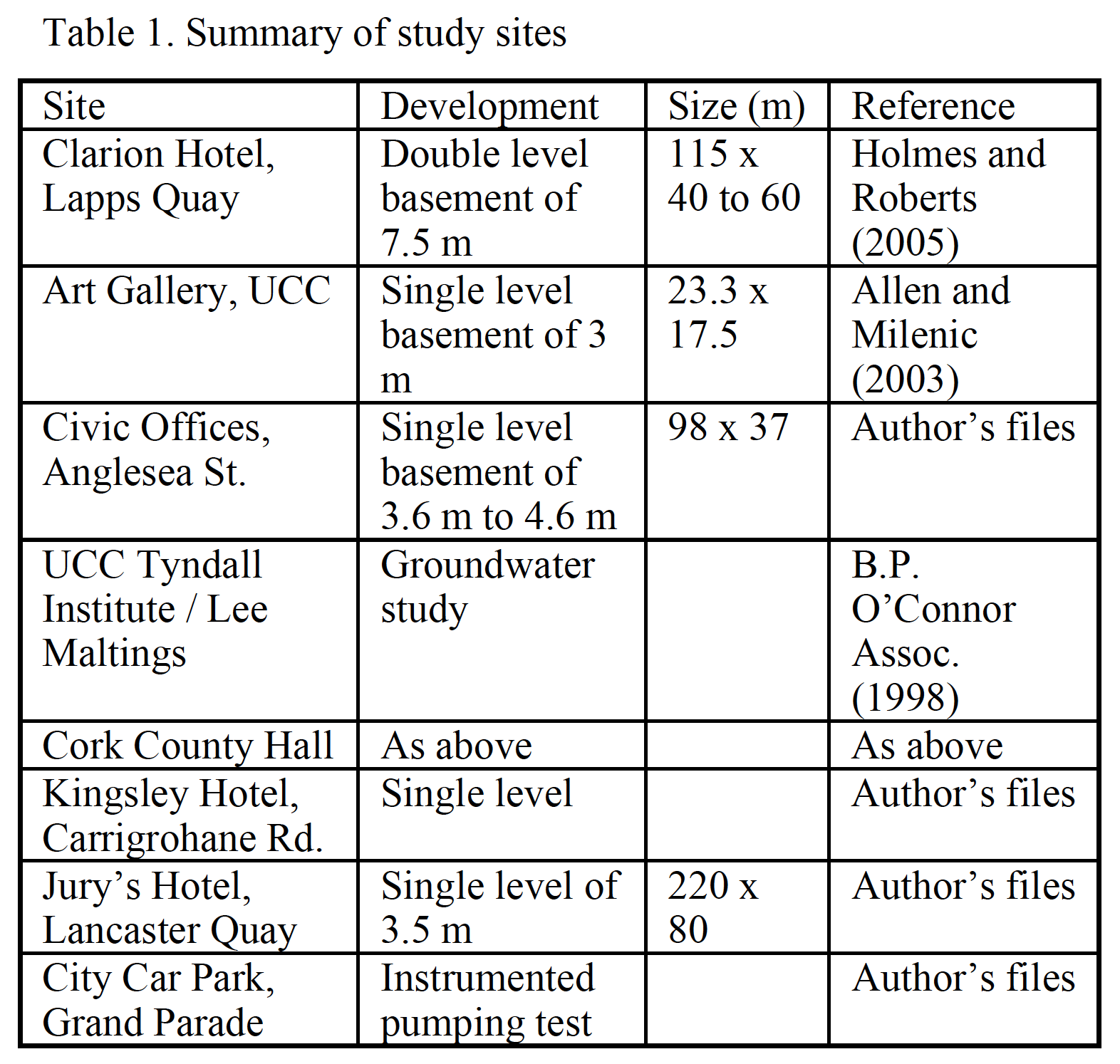
Table 1: Summary of study sites.
Ground Conditions
Made Ground
The made ground is generally granular in nature. It includes concrete and brick fragments and occasional organic lenses.
Alluvium
The alluvium comprises a mostly soft to firm sandy silt. It contains lenses and pockets of organic clay and peat. Typically the silty fraction has a water content (w) of about 35% and plasticity index (Ip) of 11%. The more organic fraction has typical w and Ip of 70% and 58% respectively.
Fluvio-glacial Gravels
These are generally described as loose becoming dense fine to coarse sub-rounded to sub-angular sandy gravel with some cobbles.
Hydrogeology and Groundwater
The Lee is at least partly in hydraulic connection with the fluvio-glacial gravels. Bank infiltration from the Lee occurs under high flow conditions. Recharge also takes place by vertical percolation through the underlying alluvium. The Lee is tidal within Cork city. In the south channel the tidal limit is close to University College Cork (UCC), see Figure 1. The aquifer is generally under a moderate subartesian pressure due to the 3 m to 4 m of alluvial sediments, which overlie the sands and gravels. Groundwater flow is generally west to east and is tidal in the city center area.
Characterisation of Fluvio-Glacial Gravels
Clarion Hotel, Lapps Quay Site
Ground conditions at the Lapps Quay site (see also geological cross section on Figure 2) comprise up to 5 m of made ground and alluvium overlying fluvioglacial gravels, see Figure 3. Below the gravels some of the site investigation boreholes proved the existence of clay, however not all the boreholes went to sufficient depth to show if this was consistent across the whole site. The fluvio-glacial gravels have standard penetration test (SPT) N values increasing from about 10 (loose) to 40 (dense) with depth. Average N is about 22.
There is little apparent variation in sand and gravel content with depth being on average 11% and 89% respectively. Particle size distribution curves, shown on Figure 4, confirm the relative uniformity of the material. There was no discernible trend of increasing or decreasing fines content with depth.
A pumping test was carried out screened in the gravels between 5m and 13 m depth, and an array of piezometers. Analysis proved difficult because of the significant tidal influence on groundwater levels and the absence of any background groundwater level monitoring data prior to pumping or recovery data following pump switch-off. A simplistic analysis suggested the permeability of the gravels was at least of the order of 10-3 m/s.
UCC Art Gallery
Similar ground investigation data for the UCC art gallery site are shown on Figures 5 and 6 respectively. The average SPT N value is higher than for Lapps Quay, being about 35, and sand content is also slightly higher at about 17%.
Particle size distribution curves fall within the range for Lapps Quay. No pumping test was carried out but Allen and Milenic (2003) estimated that the coefficient of permeability was of the order of 7×10- 3 m/s based on the particle size distribution analyses.
Other Sites
The results listed above and some data for five other sites is summarized on Table 2. In each case analysis of the borehole pump test was made difficult by the influence of tidal effects on the measured groundwater level. The range of permeability measured is relatively narrow and the representative mean is about 2.3 x 10⁻³ m/s.
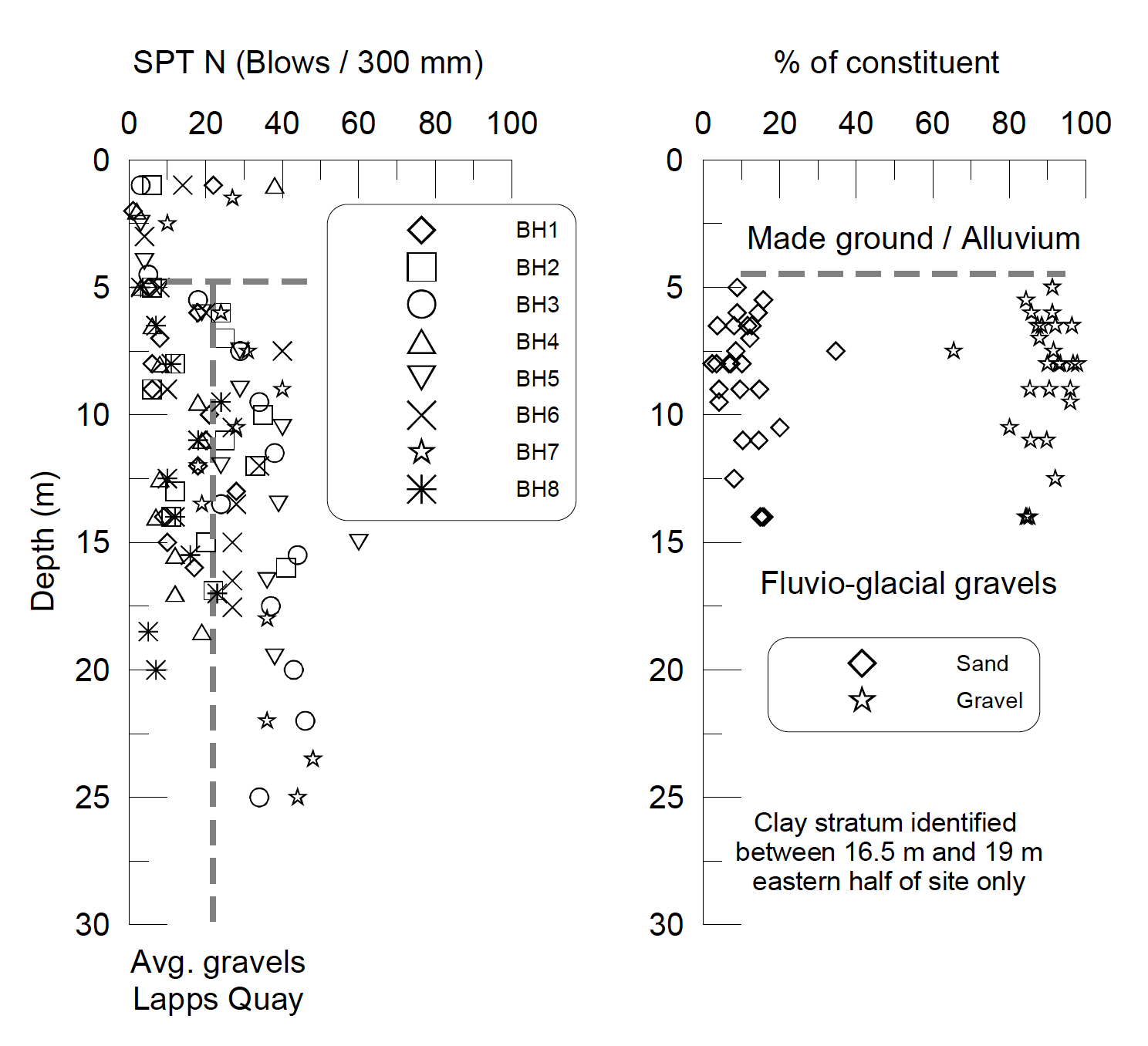
Figure 3. SPT N and sand / gravel content Lapps Quay.
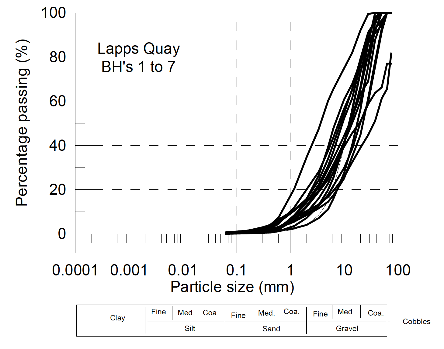
Figure 4. Particle size distribution curves for Lapps Quay.
Figure 5. SPT N and sand / gravel content UCC Art Gallery.
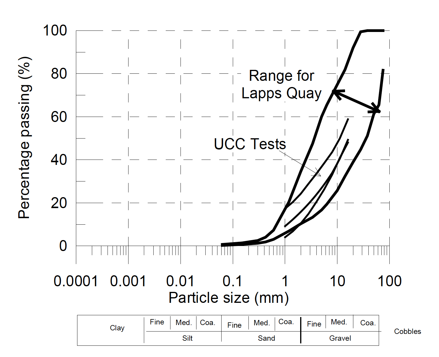
Figure 6. Particle size distribution curves for UCC Art Gallery.
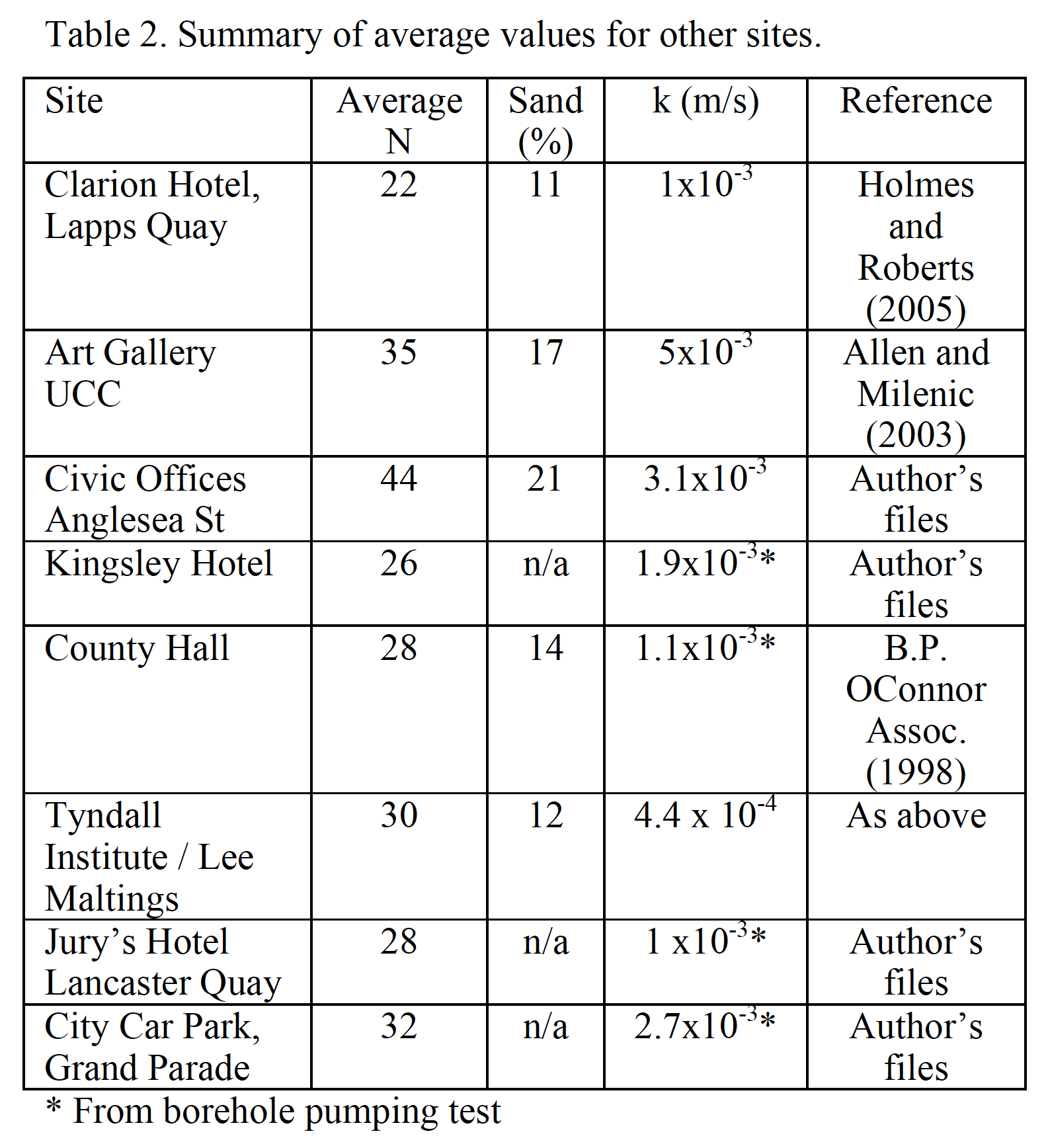
Table 2. Summary of average values for other sites.
Experience from Clarion Hotel Development, Lapps Quay
The site and ground conditions
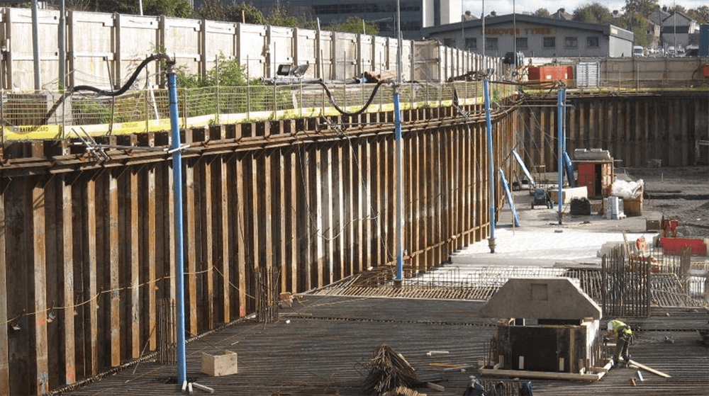
Prior to construction ground level at the site was at approximately 3 mOD (Malin) and the 7.5m deep excavation went down to –4.5 mOD. Side support was by sheet piles on three sides, forming the permanent basement walls, and, along the River Lee, by a temporary double wall cofferdam, allowing the quay wall to be removed and replaced. The sheet piles were 17 m long and were driven to a depth of -14 mOD.
Groundwater level is strongly influenced by tidal fluctuations in the River Lee. During construction the water levels fluctuated from 2 m to 4.5 m depth (+1 mOD to –1.5 mOD) in response to tidal fluctuations in the river typically in the range +2 mOD to -2 mOD.
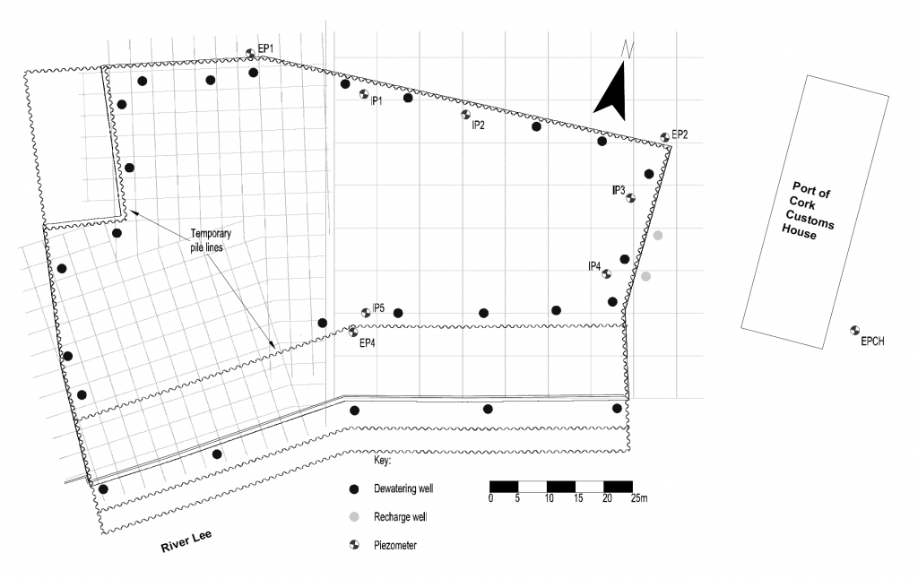
Figure 7: Site layout – Lapps Quay site.
Measured data
The water levels and flows during the initial pumping period are shown in Figure 8. The pump switch-on was a phased process with flows stepping up as wells were activated. The peak flows measured were of the order of 280 l/s. Figure 8 also shows the water levels from external piezometers (EP4 and EPCH) and an internal piezometer (IP2). Drawdown to below the target level of –5 mOD within the excavation was achieved during August. The external piezometer, EP4, was also drawn down during the pumping, the average water level being about –2.4 mOD. Therefore the difference between the average river level and the average water levels external to the excavation was approximately 2.4 m. At EPCH, 40 m from the piles, the difference was only slightly less at about 2.1 m.
Back analysis of the dewatering system was undertaken using the SEEP/W finite element model. It was found that if the gravel permeability was taken to be uniform with depth then external drawdowns in the model were significantly greater than experienced in practice. To improve the ground model, the gravel layer was subdivided into an upper layer above –12 mOD, which was taken to have a permeability of 5 x 10⁻³ m/s, and a lower layer below –12 mOD. The permeability of the lower layer was varied until a reasonable fit was obtained with the abstraction flow, internal and external drawdowns. The best fit was obtained with a permeability of the lower gravel of 6 x 10⁻⁴ m/s.
Dewatering and monitoring system
In order to allow construction of the basement in dry conditions, a dewatering system was installed to lower the groundwater levels within the excavation to below formation level. The system consisted of twenty five deep wells installed internal to the sheet piles around the perimeter of the dig. The wells were installed to the specification outlined on Table 3.
The wells were pumped with electric submersible borehole pumps with abstracted water discharged to the adjacent River Lee. Most of the wells were located within the footprint of the basement. In order to monitor the performance of the dewatering system, instrumentation was installed to measure water levels and abstraction flows. Standpipe piezometers were installed at the locations shown in Figure 7. Standpipes comprised standard 50 mm diameter liners with 3 m long screens installed to 10 m depth. Water level monitoring was also carried out in the River Lee. Abstraction flows were measured by flowmeters installed in the discharge lines. Monitoring of flows and water levels was carried out using automated data logging equipment.
Table 3: Details of wells at Lapps Quay.
Building settlement
The made ground was generally present above the standing groundwater level and so would not be influenced by the drawdown. It was considered that the gravels were sufficiently dense that any settlement would be negligible. The primary concern was the alluvium, which was soft and potentially susceptible to compression due to consolidation, even at the relatively small vertical effective stress increase induced by groundwater lowering.
The extent to which a structure would be affected by any consolidation of the alluvium would depend on the foundation bearing level of the structure. Of particular concern in this case was the Port of Cork Building, which was located within 20 m of the sheet piles (Figure 7). The foundation details of this historic building, which has a stone façade, are unknown. The building was in good condition, implying that it was probably founded on the gravels, but this could not be confirmed. Movement was monitored closely by regular levelling of targets on the adjacent structures. The monitoring did not detect any movement beyond the accuracy of the instrument. Recharge had been examined as a potential control measure but the monitoring showed that it was not required.
Experience from UCC Art Gallery Site
Conditions at the UCC Art Gallery site were different from those at Lapps Quay in that it was directly adjacent to the river and there was probably a strong connection with it through bank infiltration. The gravels in this area had proved problematic due to their high permeability during interceptor sewer construction by pipe jacking in the 1980’s.
Twelve 160 mm diameter and 11.5 m deep wells were located around the perimeter of the site. Pumps in these wells together with 4 others located in open excavations were required to maintain water levels at about 5 m depth for construction of lift shafts. Twelve pumps were required to maintain water levels at 4 m depth for the main part of the construction. All pumps were operated at maximum capacity.
No measurements of flow rate were made but it is estimated that total flow was of the order of 250 l/s to 300 l/s (Allen and Milenic, 2003). Parts of the excavation need to be supported by sheet piles to ensure stability of the excavated slopes.
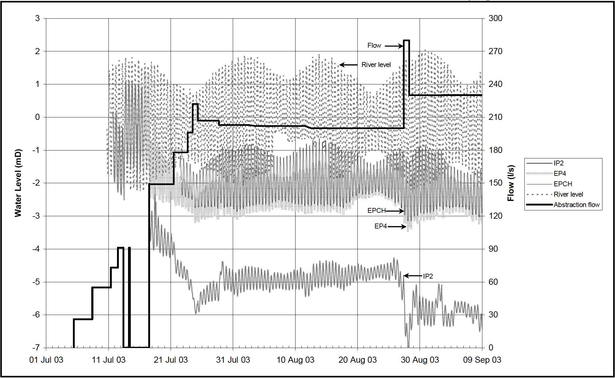
Figure 8: Monitored data – Lapps Quay.
Conclusions
The design basis information available for the basement schemes described in this paper comprised borehole logs, soil descriptions, particle size distribution curves (PSD), standard penetration (SPT) N values and in some cases borehole permeability tests and well pumping tests. The borehole data and associated test results all suggest that the gravels are of high permeability (in excess of 10-3 m/s) and are relatively uniform with depth.
Pumping tests confirm the high transmissivity of the gravels but give no indication of any variation of permeability with depth because the flow during the test is essentially horizontal. The back analysis modelling work from the Lapps Quay site indicates that the permeability of the gravels may in practice reduce by about an order of magnitude with depth. This is only apparent because of the presence of the partial cut-off provided by the sheet piles.
This view is further supported by the experience at the UCC Art Gallery excavation where a relatively shallow excavation was undertaken in open cut, without any perimeter cut-off. Inflows experienced were at least as great as those at Lapps Quay for drawdowns roughly equivalent to the external drawdown at Lapps Quay.
Any settlement risk to adjacent structures due to the external drawdown is mainly associated with under drainage of the alluvium rather than drawdown in the gravel below the alluvium. The use of a partial perimeter cut-off is clearly effective in reducing inflow rates (see above) and it will reduce the distance of influence of the drawdown. However the first 2 m or so of drawdown, sufficient to underdrain the alluvium in the immediate vicinity of the site, is unlikely to be eliminated without a virtually complete cut-off or provision for recharge.
Acknowledgements & References
Acknowledgements
The authors would like to thank P J Hegarty & Sons and Walsh Goodfellow Consulting Structural and Civil Engineers for their kind permission to publish the information on the Lapps Quay site. Mr. Niall Fitzsimons of Niall Fitzsimons and Co. kindly provided ground information data for several of the sites.
References
Allen, A. and Milenic, D. 2003. Drainage problems during construction operations within a buried valley gravel aquifer. RMZ – Materials and Geoenvironment, Vol. 50 (1): 1 – 4.
B.P. O’Connor Associates. 1998. Report on the assessment of the thermal potential of shallow groundwater in gravels beneath the River Lee floodplain.
Holmes, G. and Roberts, T. 2005. Lapps Quay Development, Cork. Dewatering and Instrumentation – A Case Study. Proceedings IAH Groundwater Seminar, Tullamore, Ireland, April, 8p.
Milenic, D. and Allen, A. 2002. Lee Buried Valley – A significant Groundwater Resource, SW Ireland. Proceedings XXXII IAH Congress, Mar del Plata,
Argentina, Groundwater and Human Development, Bocanegra et al. (eds.), 8p.
Preene, M., Roberts, T.O.L., Powrie, W. and Dyer, M.R. 2000. Groundwater control – design and practice. Construction Industry Research and Information Association, CIRIA C515, London, 2000.
Reilly, T. and Sleeman, A. 1977. Geology of the Ringaskiddy Basin. Unpublished report for Cork Harbour Commissioners. Geological Survey of Ireland.
Whittow, J.B. 1974. Geology and Scenery in Ireland. Pelican, Bungay, Suffolk.
Link
To read the full, original published paper, please click on the link below: